DVS-7000AE IM
5-7
5-1. Switch Settings on Boards and LEDs Description
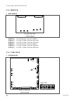
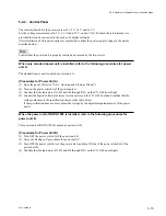
COP1
(F2) :
This is used to select the mode corresponding to the synchronized signal that is connected to the
SWITCHER on the rear panel. Normaly, opened under.
COP2
(G3) :
Normaly, short-circuit the “NOR” side.
S1
(G12) : RESET switch
This switch is used to forcibly restart the SYSTEM by the hardware. The unit is operated the same as the
operation when turning the POWER ON.
S2
(H12) : ABORT switch
This switch is used for the adjustment in the factory.
S3
(J12) : SUB ABORT switch
This switch is used for the adjustment in the factory. If pressing this switch after selecting the S5 switch
on the CPU-263 board to the SUB CPU flash memory access protection mode, clean the content of the
flash memory for stored-program.
S4
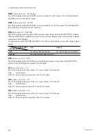
(B5) : MAIN CPU switch
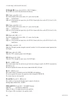
This switch is used to select the operation of MAIN CPU. After changing the selection, to start the
operation re-press the S1 of the RESET switch on the CPU-263 board or re-turn the power on.
Setting : All OFFs.
n
The addresses of the knobs are shown by marks.
(1) Selection 1 under normal status
When starting up the system, the diagnostic program does not run. Just after turning the power on,
the system starts up.
(2) Selection 2 under normal status.
When starting up the system, diagnostic program runs. After turning the power on, it is necessary for
about ten seconds until the system starts up.
Under normal status, all settings are OFFs.
ON
1
2
3
4
5
6
7
8
ON
1
2
3
4
5
6
7
8


