1-33
FVS-1000 MMP1
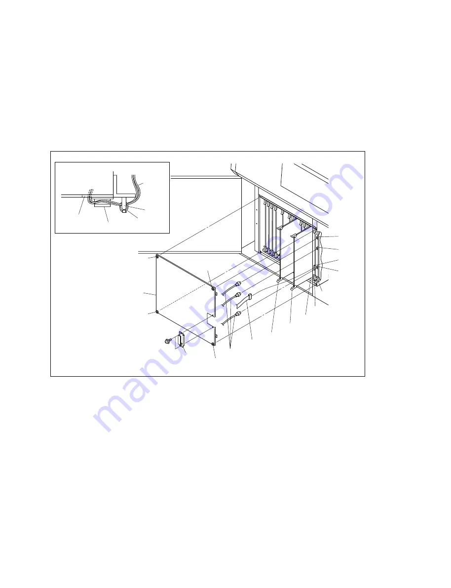
(4) Connect the flat cable with the CN6027 connector on the MY-89 board.
(5) Connect the three coaxial cables with the CN402, 702 and 120 connectors on the ADC-36 board.
(6) Remove the CN-1600 board inserted between the MY-89 board and CC-78 board, and insert the DP-
345 board along the guide rail.
In the same way, remove the CN-1600 board inserted between the EN-137 board and SY-256 board,
and insert the CN-2243 board along the guide rail.
m
.
When inserting the processor board, confirm the processor board name on the label.
.
Insert the processor board completely until the connector is connected.
(7) Connect the three coaxial cables with the CN402, 702 and 120 connectors on the ADC-36 board.
(8) Connect the flat cable with the CN6027 connector on the MY-89 board.
(9) Install the front cover, then tighten four screws.
n
Pull out the flat cable and the coaxial cables connected with the processor boards through the notch of
the front panel, then fix with the clip plate and two screws (PSW3
x
6).
Clip plate
Top view
Notch
Harness
band
Handle
Cables
Clip plate
Coaxial cables
Flat cable
PSW3
x
6
ADC-36 board
CN402
CN702
CN102
CN6027
Label
MY-89 board
DP-345 board
CN-2243 board
Screw
(with stopper)
Screw(with stopper)
Screw(with stopper)
Front cover
Screw(with stopper)
1-11. Installation of Optional Units


