1-34
FVS-1000 MMP1
Rear side
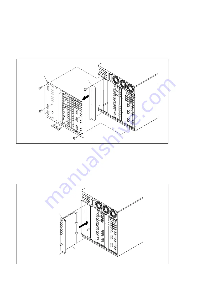
(1) Remove the five screws and remove the duct cover from the rear of the unit. (for UC/CE model only)
(2) Remove the 10 screws and remove the rear shield from the processor assembly. (for UC/CE model
only)
(3) Loosen 2 screws (with stopper) used for the third and fourth slot from the left at the rear, and then
remove the blank panel. (When it is a piece of large blank panel, remove itself.)
(4) Insert the DIF-120 board along with the 3rd guide rail from the left.
Use the 3rd and 4th slot for the panel.
(5) Tighten the upper and lower knobs one after the other several times, then insert the connector
completely until the connector is connected.
n
Be sure to tighten the two screws one after the other.
If one screw is tightened completely first, there is a possibility of damaging the connector or screw.
Screws
Rear shield
(for UC/CE model only)
Cover
Screws
Screws
Screw
Screws
DIF-120 board
Screw(with stopper)
Screw(with stopper)
1-11. Installation of Optional Units


