2-9
BKM-120D/127W/129X/142HD
485
±
10 mV
PB
9.
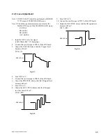
Turn OFF ACC.
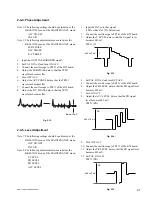
10. Connect the oscilloscope to TP471 of the BW board.
11. Adjust the PR LEVEL data so that the PR signal level
becomes 485 mV.
TP471 (PR)
Fig. 2-20.
2-5-3. Level Adjustment
Note 1: ON/OFF of ACC should be performed with BKM-
127W menu of MAINTENANCE menu.
Note 2: The following adjustment menus are below the
BKM-127W menu of the MAINTENANCE menu.
Y LEVEL
PB LEVEL
PR LEVEL
ACC LEVEL
1.
Input the NTSC YC color bar signal.
2.
Connect the oscilloscope to TP261 of the BW board.
3.
Adjust the Y LEVEL data so that the Y signal level
becomes 658 mV.
TP261 (Y)
Fig. 2-18.
4.
Turn OFF ACC.
5.
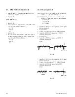
Connect the oscilloscope to TP421 of the BW board.
6.
Adjust the PB LEVEL data so that the PB signal level
becomes 485 mV.
7.
Turn ON ACC.
8.
Adjust the ACC LEVEL data so that the PB signal
level becomes 485 mV.
TP421 (PB)
Fig. 2-19.
485
±
10 mV
PR
658
±
10 mV
Y
Summary of Contents for BKM-120D
Page 12: ...1 8 BKM 120D 127W 129X 142HD ...
Page 60: ...7 6 BKM 120D 127W 129X 142HD 7 6 2 3 4 5 A B C D E F G H 1 BD 1 4 BKM 120D BD 1 4 BKM 120D ...
Page 61: ...7 7 BKM 120D 127W 129X 142HD 7 7 2 3 4 5 1 A B C D E F G H BD 2 4 BKM 120D BD 2 4 BKM 120D ...
Page 62: ...7 8 BKM 120D 127W 129X 142HD 7 8 2 3 4 5 A B C D E F G H 1 BD 3 4 BKM 120D BD 3 4 BKM 120D ...
Page 63: ...7 9 BKM 120D 127W 129X 142HD 7 9 2 3 4 5 1 A B C D E F G H BD 4 4 BKM 120D BD 4 4 BKM 120D ...
Page 74: ...7 20 BKM 120D 127W 129X 142HD 7 20 2 3 4 5 A B C D E F G H 1 BW 1 2 BKM 127W BW 1 2 BKM 127W ...
Page 75: ...7 21 BKM 120D 127W 129X 142HD 7 21 2 3 4 5 1 A B C D E F G H BW 2 2 BKM 127W BW 2 2 BKM 127W ...

