2-14
BKM-120D/127W/129X/142HD
1-3. PR LEVEL Adjustment
Adjustment
Standard
Adjusting Point
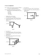
• Input the 100% color bar signal
TP307 (PR OUT) output level:
The adjustment menu is located in
(100% White Ref. 100% Saturation)
the lower layer of BKM-120D of
into the SDI input terminal.
the MAINTENANCE menu.
• Connect an oscilloscope to TP307
PR LEVEL
(PR OUT).
2. Digital Free Run Adjustment
Adjustment
Standard
Adjusting Point
Step 1
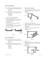
• No input signal
TP101 (DACLK) output frequency:
The adjustment menu is located in
• Connect an frequency counter to
27.0
±
0.15 MHz
the lower layer of BKM-120D of
TP101 (DACLK).
the MAINTENANCE menu.
DA-FV
Step 2
• Connect an frequency counter to
TP102 (DBCLK) output frequency:
The adjustment menu is located in
TP102 (DBCLK).
27.0
±
0.15 MHz
the lower layer of BKM-120D of
the MAINTENANCE menu.
DB-FV
3. D1 H Phase Adjustment
Adjustment
Standard
Adjusting Point
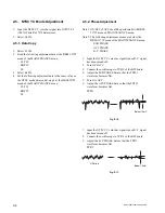
• Input the D1 100% white signal (525/60).
The adjustment menu is located in
• Connect the CH1 probe of the
the lower layer of BKM-120D of
oscilloscope to TP305 (Y OUT).
the MAINTENANCE menu.
• Connect the CH2 probe of the
C
oscilloscope to CN401 20a (H SYNC).
CL
P
645
±
10 mVp-p
H SYNC
Y out
H sync
Y out
A
A
Spec A : = 8.5
±
0.1
µ
Sec
Summary of Contents for BKM-120D
Page 12: ...1 8 BKM 120D 127W 129X 142HD ...
Page 60: ...7 6 BKM 120D 127W 129X 142HD 7 6 2 3 4 5 A B C D E F G H 1 BD 1 4 BKM 120D BD 1 4 BKM 120D ...
Page 61: ...7 7 BKM 120D 127W 129X 142HD 7 7 2 3 4 5 1 A B C D E F G H BD 2 4 BKM 120D BD 2 4 BKM 120D ...
Page 62: ...7 8 BKM 120D 127W 129X 142HD 7 8 2 3 4 5 A B C D E F G H 1 BD 3 4 BKM 120D BD 3 4 BKM 120D ...
Page 63: ...7 9 BKM 120D 127W 129X 142HD 7 9 2 3 4 5 1 A B C D E F G H BD 4 4 BKM 120D BD 4 4 BKM 120D ...
Page 74: ...7 20 BKM 120D 127W 129X 142HD 7 20 2 3 4 5 A B C D E F G H 1 BW 1 2 BKM 127W BW 1 2 BKM 127W ...
Page 75: ...7 21 BKM 120D 127W 129X 142HD 7 21 2 3 4 5 1 A B C D E F G H BW 2 2 BKM 127W BW 2 2 BKM 127W ...


