5(E)
Function and Location of Parts and Controls
Front panel
POWER
CALL
SAT OFF-ON
V MOD SAW
B FLARE
KNEE SLOPE
SATURATION
M BLK GAMMA
G FLARE
KNEE POINT
ECS
M GAMMA
R FLARE
DTL LEVEL
PANEL
ACTIVE
STANDARD
MASTER GAIN
FILTER
MONITOR
SELECT
SHUTTER
MASTER BLACK
IRIS
OUTPUT
AUTO SETUP
W/B BAL
SCENE FILES
AUTO
KNEE
ABSOLUTE
INCOM
CABLE
ALARM
"
1
CAM
ON
PROD
PGM
PGM
SEQ
ENC
CHAR
R/G/B
ON
OFF
MENU
B
G
R
MIC –
OFF
PREV
TEST
STORE
BARS
START
BREAK
RECALL
CANCEL
v
v
V
LOCK
CAM
ECS
RELATIVE
AUTO
EXTENDER
DISPLAY
FILTER
CANCEL
v
V
ON
ND
CC
OFF
SHUTTER
1
3
2
WHT A
WHT B
WHITE
AWB
ABB
•
•
•
•
•
•
•
OPEN
SHORT
MAIN
BLACK
•
•
•
•
•
•
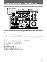
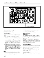
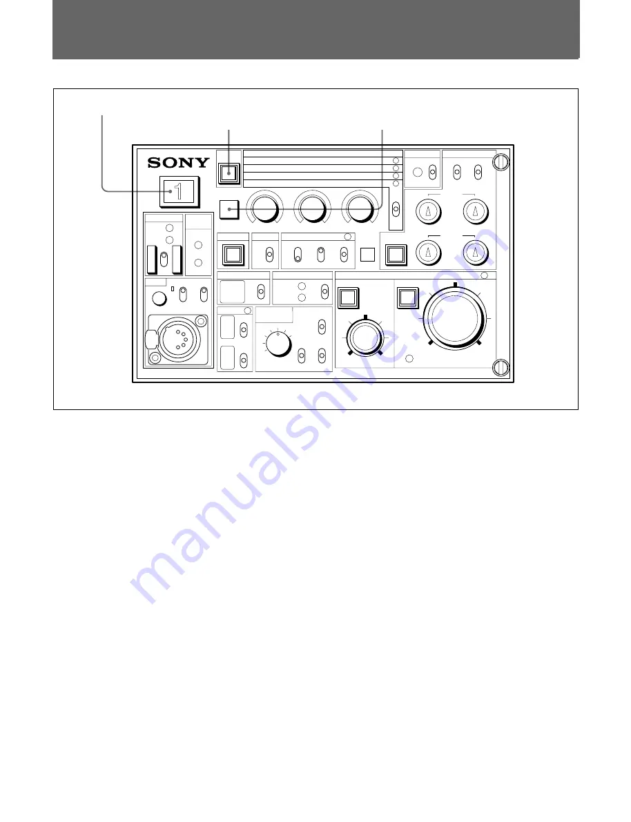
1
Camera number/tally indicator
2
PANEL ACTIVE button
3
CALL button
1
Camera number sheet/tally indicator
Lights red when the red tally signal is input (e.g. when
the video signal from the video camera connected to
the CCU-550 series unit goes on air). When the CALL
button on the video camera, MSU-700A, RCM-700
series remote control panel, or an optional BKP-5973
is pressed, the indicator lights if it is not lit, and goes
off if it is lit.
The indicator lights green when the green tally signal
is input (e.g. when the video signal from the camera
connected to the CCU-550 series unit goes off air).
Attach the supplied number sheet here to indicate the
camera number.
2
PANEL ACTIVE button
When an remote control unit is connected, press to
select the device which controls the camera.
The BKP-5973 controls the camera when this button is
lit.
3
CALL button
When you press this button, the TALLY indicator on
the video camera and in the viewfinder and the tally
indicator on the remote control panel connected to the
CCU-550 series unit light up. The tally indicator on
the BKP-5973 also lights up when you press this
button, and goes off when the CALL button is pressed
while it is lit.


