– 2 –
Specifications ........................................................................... 1
1. SERVICING NOTE
....................................................... 2
2. GENERAL
Features .............................................................................. 3
Precautions ......................................................................... 3
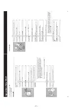
Operation Flow Chart ........................................................ 4
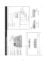
Location and Function of Controls .................................... 5
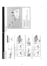
Preparation ......................................................................... 6
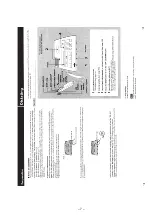
Dictating ............................................................................. 7
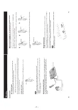
Transcribing ....................................................................... 9
Erasing ............................................................................. 11
Alarm System .................................................................. 12
Telephone Recording ....................................................... 12
3. DISASSEMBLY
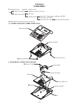
3-1. Cabinet (Rear) Assy , Cabinet (Front) ASSY ........... 13
3-2. Main Board, Connecter (12P) Board ........................ 13
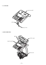
3-3. LED Board ................................................................ 14
3-4. Mechanism Deck ...................................................... 14
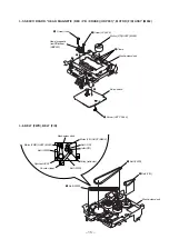
3-5. Servo Board, “Head Magnetic (REC/PB/Erase)
(HRP901)”, Motor (F/R) ASSY (M902) .................. 15
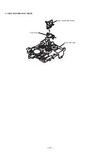
3-6. Belt (FWD), Belt (F/R) ............................................. 15
3-7. Motor (FWD) ASSY(M901) .................................... 16
4. MECHANICAL ADJUSTMENTS
.......................... 17
5. ELECTRICAL ADJUSTMENTS
............................ 18
6. DIAGRAMS
6-1. Explanation of IC Terminals ..................................... 19
6-2. Block Diagram .......................................................... 21
6-3. Printed Wiring Boards (Servo Section) .................... 23
6-4. Schematic Diagram (Servo Section) ......................... 25
6-5. Printed Wiring Boards (Main Section) ..................... 28
6-6. Schematic Diagram (Main Section) ......................... 31
7. EXPLODED VIEWS
7-1. Cabinet Section ......................................................... 35
7-2. Mechanism Deck Section (1) (MB-87-59) ............... 36
7-3. Mechanism Deck Section (2) (MB-87-59) ............... 37
8. ELECTRICAL PARTS LIST
.............................
38
SAFETY-RELATED COMPONENT WARNING!!
COMPONENTS IDENTIFIED BY MARK
0
OR DOTTED LINE WITH
MARK
0
ON THE SCHEMATIC DIAGRAMS AND IN THE PARTS
LIST ARE CRITICAL TO SAFE OPERATION.
REPLACE THESE COMPONENTS WITH SONY PARTS WHOSE
PART NUMBERS APPEAR AS SHOWN IN THIS MANUAL OR IN
SUPPLEMENTS PUBLISHED BY SONY.
TABLE OF CONTENTS
Notes on chip component replacement
• Never reuse a disconnected chip component.
• Notice that the minus side of a tantalum capacitor may be dam-
aged by heat.
SECTION 1
SERVICING NOTE
NOTES FOR REPAIRING
1. POWER (S101) Switch
The POWER switch is not for turning ON/OFF the power
source. Pay attention when repairing even the POWER
switch is turned off.
• The states when turning off the POWER switch are as
follows.
a. Motors (M901, 902) will be stopped.
b. Plungers (PM901 to 903) will be turned off.
c. Amplifier output will be cut-off by muting on.
The above items from “a” to “c” are controlled by the
microcomputer which makes the pin 38 of IC109
(microcomputer) become Low level.
2. Be careful the short circuit when repairing since the power
supply circuit does not have any protection devices.
Please note that the current shut down (D108) will be work
when the power connected to the opposite way.
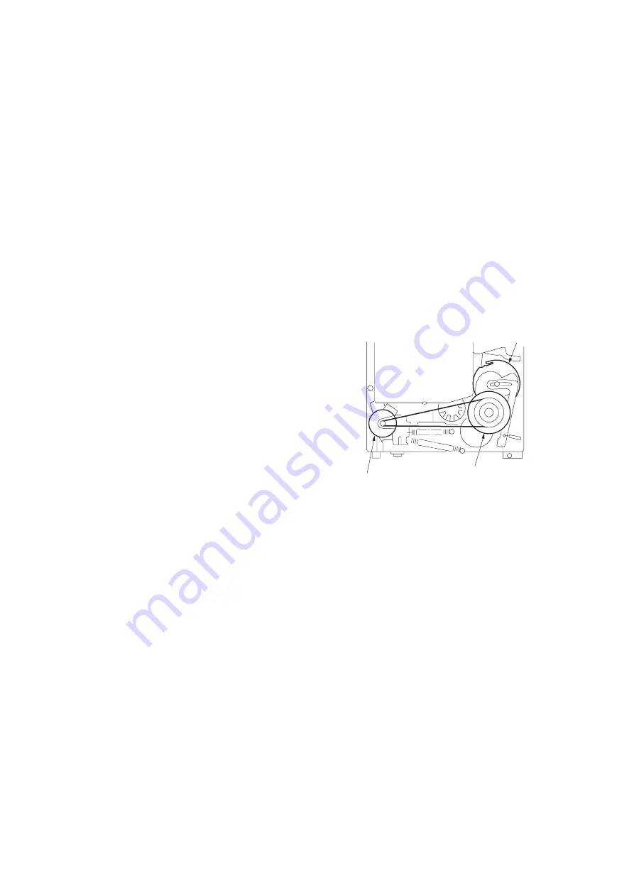
3. Crack of Flywheel Gear and Cam Gear
Do not turn the Flywheel counterclockwise.
The flywheel gear and cam gear may be crack when turn the
flywheel counterclockwise.
cam gear
motor (FWD) (M901)
flywheel
Summary of Contents for BM-87DST Marketing
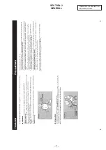
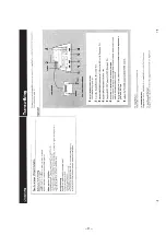
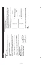
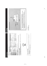
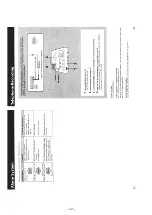
Page 3: ... 3 SECTION 2 GENERAL This section is extracted from instruction manual ...
Page 4: ... 4 ...
Page 5: ... 5 ...
Page 6: ... 6 ...
Page 7: ... 7 ...
Page 8: ... 8 ...
Page 9: ... 9 ...
Page 10: ... 10 ...
Page 11: ... 11 ...
Page 12: ... 12 ...
Page 16: ... 16 3 7 MOTOR FWD ASSY M901 3 1 2 Motor FWD ASSY M901 Mechanism deck Cushion M ...
Page 21: ... 21 22 BM 87DST 6 2 BLOCK DIAGRAM Note Signal path E PB a REC ...
Page 31: ... 43 BM 87DST MEMO ...

