LCD DIGITAL COLOR TELEVISION
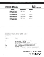
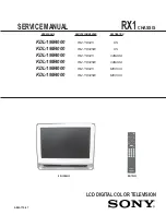
SERVICE MANUAL
RX1
CHASSIS
MODEL NAME
REMOTE COMMANDER
DESTINATION
9-883-775-07
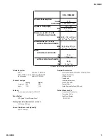
KDL-19M4000
RM-YD025
US
KDL-19M4000
RM-YD025W
US
KDL-19M4000
RM-YD025
CANADA
KDL-19M4000
RM-YD025W CANADA
KDL-19M4000
RM-YD025
MEXICO
KDL-19M4000
RM-YD025W MEXICO
HISTORY INFORMATION FOR THE FOLLOWING MANUAL:
ORIGINAL MANUAL ISSUE DATE: 3/2008
☛
:UPDATED ITEM
REVISION
DATE
SUBJECT
3/2008
No revisions or updates are applicable at this time.
4/2008
Reissue entire manual to include PWBs for G Board (Power Supply)
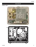
Added Line Art illustration for Wire Dressing
Added PNs for Colored Bezels to Exploded View section.
5/2008
Corrected instructions for 2-1. Resetting to Factory Defaults After Board Replacement.
Replaced
page
17.
5/2008
Corrected PNs for White and Black Front Bezel Assemblies. Replaced page 43.
10/2008
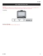
Removed Self Diagnosis logo from Front Cover and Self Diagnostic Function page.
Replaced pages 2 and 10.
12/2008
Corrected H2 Board and H3 Board information. Replaced pages 13, 15, 16, 18, 21, & 38-39.
8/2009
Corrected H2 Board and H3 Board information. Replaced pages 3, 13, 15, 16, 18, 21, 38, 39, & 43.


