SECTION 2
SELF DIAGNOSTIC FUNCTION
RM-GD020, RM-CD013
KDL-32, 40, 46 CX523
KDL- 22, 32, 40, 46 CX520
S
f
RM-GD020
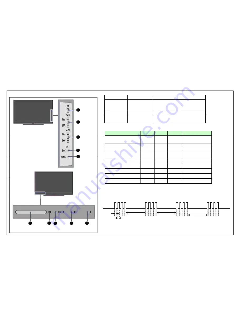
2-1. Overview of Control Buttons
1
Power
2-2 LED Display Specification
LED Type
Description
Remark
POWER
GREEN:LED
RED: LED
Green Lights at Power On
Red Lights when recording ( only
applicable in Japan and Europe models)
STANDBY
RED: One LED
Red Lights during standby
2
Program
2-3. LED Display Control
g
g
y
TIMER/PIC OFF
ORANGE/GREEN: Orange Lights during Timer activation
and Green Lights during Picture Off.
Two LEDs
Blinking Pattern
Status
Picture Off/
Connecting/Tim
Standby LED Power /REC
3
4
5
Volume
Input Select/
Home
Enter
Off
Off
Self Diagnosis
Off
RED Blink
Off
Standby
( by remote control off only )
Off
RED Lit
Refer to Blinking pattern of Self
Diagnosis mode
Power On
Off
Off
GREEN
Connecting/Tim
Power Off
( by power button or AC off )
Off
Off
5
Home
Error of panel ID
ORANGE
Blink
Off
GREEN Blink
Off
Test Reset finish
ORANGE Lit
Red
GREEN Lit
Software Updating
ORANGE
Blink
RED Lit
Software Updating finish
ORANGE Lit
Off
GREEN Lit
Aging mode
Off
Off
GREEN Blink
Blinking:0.5sec On / 0.5sec Off
Off
End of Aging mode
Off
GREEN Blink
Blinking:5sec On / 1sec Off
Blinking:3sec On / 3sec Off
Blinking:0.5sec On / 0.5sec Off
Diagnosis mode
2-4. LED Pattern
When safety shutdown occurs, Standby LED display reports the cause by using the lightning
patterns as indicated below.
[REC][Sleep Timer][Power ON]
ORANGE
Off
RED
[Picture Off][On Timer][REC][Power ON]
GREEN
Off
RED
Blink
p
3.0sec
3.0sec
0 5sec
0.
5sec
3.0sec
6
8
9
10
Remote
Sensor
Picture
Timer
Off/Standby
Indicator
Power
Indicator
6
6
7
IR Logo
0.5sec
Example: The figure above shows LED display when SHUTDOWN is caused by Balancer
Error. It repeats flashing for a specified number of times in 0.5sec/cycle and has a 3 seconds
interval of lighting off. Please note that a 3 seconds interval of lighting off is fixed regardless of abnormal state types.
-7-
www.eletronicageral.com.br


