background image

KDL-24R400A/32R400A 16

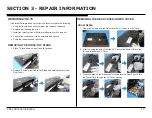
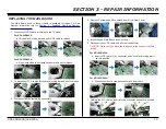
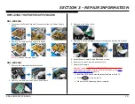
SECTION 3 - REPAIR INFORMATION

8.  Update the Software.

After ALL repairs UPDATE the SOFTWARE to the latest version. 

Instructions are included with the Software package on the 

Sony 

Authorized Service Portal

 website.

a.  Insert the USB device with the latest Software into the TV.
b.  Press 

POWER

 to turn on the TV.

c.  Wait until the Software update is complete.

9.  After update is complete, press 

POWER

 to turn off the TV.

10. Access 

Service Mode

 by pressing the following buttons within 1 

second of each other:

DISPLAY


Channel


5


Volume


+


POWER

Sound Adjustment

>>

Wide Band Tuning

>>

Range Scan…

>>

Self diagnosis history

>>

Status Information…

>>

LVDS Spectrum(%0)

<[

30

]>

Low of HPD

<[

5

]>

TVD_MCDONE_CNT

<[

20

]>

Demo Special

>>

Bypass AVI Info Detect

<[

On

]>

Panel Selection

<[

   21_LSY320AN02     

]>

UART Selection

No Log

SERIAL NUMBER EDIT

MODEL NAME EDIT

[</>]Set [Home] Exit

Service Mode

11.  Press 

 until 

Panel Selection

 is selected.

Sound Adjustment

>>

Wide Band Tuning

>>

Range Scan…

>>

Self diagnosis history

>>

Status Information…

>>

LVDS Spectrum(%0)

<[

30

]>

Low of HPD

<[

5

]>

TVD_MCDONE_CNT

<[

20

]>

Demo Special

>>

Bypass AVI Info Detect

<[

On

]>

Panel Selection

<[

   21_LSY320AN02     

]>

UART Selection

No Log

SERIAL NUMBER EDIT

MODEL NAME EDIT

[</>]Set [Home] Exit

Service Mode

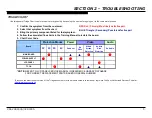
12. Press   or   to select the correct Panel Code for theTV model. 

(Use the table below for reference).

Model Name

Panel Code

KDL-24R400A

21_LYS320AN02

23_V236BJ1 

KDL-32R400A


CAUTION: Select ONLY the correct Panel Code. 

13. Locate the Serial Number for the TV on the side of the Rear Cover.

MODEL NO

KDL-32R400A

SERIAL NO

6000001

Summary of Contents for BRAVIA KDL-32R400A

Page 1: ... Digital Color TV 9 883 498 02 RB1FK Chassis Segment BA Version Date Subject 1 0 01 27 2013 Original Manual Release Date 2 0 02 08 2013 Updated Section 3 Repair Information Replaced pages 13 21 MODEL COMMANDER DESTINATION KDL 24R400A RM YD092 LA MX KDL 32R400A RM YD092 US CND LA MX KDL 32R400A ...

Page 2: ...o Distortion Flowchart 12 Section 3 Repair Information 13 Repairing the TV 13 Removing the Table Top Stand 13 Removing the Rear Cover Lower Cover 13 KDL 24R400A 13 KDL 32R400A 14 Replacing the Main Board 15 Replacing the Power Supply Board 19 KDL 24R400A 19 KDL 32R400A 19 Removing the Switch Unit 20 Removing the Speakers 20 Removing the Bezel and H Board Assembly 20 KDL 24R400A 20 KDL 32R400A 21 S...

Page 3: ...ited CAUTIONS AND WARNINGS ATTENTION Ces instructions de service sont à l usage du personnel de service qualifié seulement Pour prévenir le risque de choc électrique ne pas faire l entretien autre que celui contenu dans le Mode d emploi à moins que vous soyez qualifié faire ainsi ALERTE Afin d eviter tout risque d electrocution provenant d un chássis sous tension un transformateur d isolement doit...

Page 4: ...ck leakage as described in Leakage Test LEAKAGE TEST The AC leakage from any exposed metal part to earth ground and from all exposed metal parts to any exposed metal part having a return to chassis must not exceed 0 5 mA 500 microamperes Leakage current can be measured by any one of three methods 1 A commercial leakage tester Follow the manufacturers instructions provided with the tester 2 A batte...

Page 5: ... mVrms typical PCM Dolby Digital optical signal USB Photo Music and Video SECTION 1 SPECIFICATIONS AND LAYOUTS KDL 32R400A KDL 24R400A W 0 4 W 0 6 23 6 24 class 31 5 32 class 8 9 5 0 0 8 mm 0 0 1 5 3 0 0 1 0 4 with stand mm 731 461 163 4 6 3 4 3 8 5 5 6 7 1 4 4 1 3 7 100 100 8 3 1 0 5 8 2 1 8 4 Model name Power and others Power requirement 110 240 V AC 50 60 Hz USA Canada Mexico 120 V AC 60 Hz Pow...

Page 6: ...R400A 2 SECTION 1 SPECIFICATIONS AND LAYOUTS BOARD LAYOUT KDL 24R400A TCON H BOARD POWER SUPPLY BOARD GE24 SWITCH UNIT MAIN BOARD A BOARD KDL 32R400A TCON SWITCH UNIT H BOARD MAIN BOARD A BOARD POWER SUPPLY BOARD GL3 ...

Page 7: ...KDL 24R400A 32R400A 3 SECTION 1 SPECIFICATIONS AND LAYOUTS WIRE DRESSING KDL 24R400A KDL 32R400A ...

Page 8: ...sure what is causing the television to shut down If the screen displays a 0 no error has occurred 1 Press POWER to turn on the TV and then turn it off again 2 Press the following buttons on the Remote Commander within 1 second of each other DISPLAY Channel 5 Volume POWER NOTE This differs from accessing Service Adjustments Mode Volume SECTION 2 TROUBLESHOOTING SelfDiagnosis Supported model Back 00...

Page 9: ...ent listed for that symptom 5 Chart Color Code Power Audio 2X 3X 5X 6X Dead set No Video Whole Screen Distortion Isolated Area Distortion No Audio MAIN BOARD POWER SUPPLY LCD PANEL TCON Video Protection Modes 4 Follow the associated flowcharts in the Training Manual to isolate the board Board NOTE REFER TO LCD PANEL SERVICE MANUAL IN REFERENCE LIBRARY DATABASE FOR CORRECT REPLACEMENT PARTS BASED O...

Page 10: ...DIAGRAM COMPONENT COMPOSITE RF COMPOSITE HDMI 1 PC HD15 POWER SUPPLY SWITCH UNIT LED IR RX LCD PANEL TCON LED BACKLIGHTS A H L R ANALOG AUDIO OUT OPTICAL AUDIO OUT MT5389 A V DECODER A V PROCESS TUNER USB 1 HDMI 2 LVDS AC IN CLASS D AUDIO AMP GL3 32 HEADPHONE AUDIO OUT GE24 24 MAIN BOARD ...

Page 11: ...12V PWM BL_ERR BL_ON 8 11 12 13 14 NC 15 AC IN N AC IN H 1 2 CN2 A STBY 3 3V GND VCC 12V 1 2 7 11 3 8 BL PWM AC_DET 4 5 CN201 TCON_VCC 10 AUDIO_12V 12 POWER_ON 6 BL_ERR 13 BL_EN 14 CN1 LCD PANEL TCON LED BACKLIGHTS LED 1 1 LED 2 2 CN3 GE24 24 3 4 LED 3 LED 4 NC 5 6 7 VLED 28 8V 8 9 NC LED 5 10 11 12 LED 6 LED 7 LED 8 POWER SUPPLY MAIN BOARD ...

Page 12: ...L_CNTRL BLKT_EN AUDIO_12V 6 8 9 11 10 AUDIO_12V NC BKL_ERR VCC_12V 11 12 13 15 14 NC 16 AC IN N AC IN H 1 2 CN6401 A STBY 3 3V GND VCC 12V 1 2 7 11 3 8 BL PWM AC_DET 4 5 CN201 TCON_VCC 10 AUDIO_12V 12 POWER_ON 6 BL_ERR 13 BL_EN 14 GL3 32 CN6101 LCD PANEL TCON LED BACKLIGHTS LED 1 LED 2 CN6801 POWER SUPPLY MAIN BOARD ...

Page 13: ...front panel light steady Press power button while monitoring pin 4 of CN6401 on Power Supply Board High 3 3V on pin 4 Yes No Main Board High 3 3V on pin 6 Yes No Unplug TV from AC power Wait at least 20 seconds and re apply AC power 24 Press power button while monitoring pin 3 of CN2 on Power Supply Board High 3 3V on pin 3 High 3 3V on pin 2 Yes No Power Supply Board Power Supply Board Yes Power ...

Page 14: ...fer to Section 4 Exploded View Part Number Information on page 22 STANDBY LED BLINKING FLOWCHART Protect Shutdown Standby LED Blinking No Yes No Yes 2X Main Board 3X 5X No Yes LCD Panel 6X Yes Power Supply Board SONY logo appears before shutdown Yes No LCD Panel Power Supply Board ...

Page 15: ...loded View Part Number Information on page 22 NO VIDEO FLOWCHART No Video Backlights turned on Unplug LVDS connector at TCON while unit is running This may need to be done more than once Any flashes seen on screen Yes No Any OSD graphics present No Main Board No LCD Panel Yes Yes Main Board LCD Panel ...

Page 16: ...HART Video Distortion Is distortion across entire screen Any horizontal lines No No Yes Yes Improper of missing colors Yes Main Board No Vertical lines or bars No Yes Lines move when wide mode changed Yes No LCD Panel Main Board LCD Panel Any single or isolated vertical lines Yes LCD Panel More than 1 vertical band No Yes LCD Panel Uneven brightness LCD Panel Yes No ...

Page 17: ...adjustments and checks 5 Verify the repair resolved the issue REMOVING THE TABLE TOP STAND 1 Place TV face down on a soft and flat surface 2 Remove 2 screws from Table Top Stand and carefully detach from Rear Cover REMOVING THE REAR COVER LOWER COVER KDL 24R400A 1 Remove 6 screws from the Rear Cover and 1 screw from AC Cover 2 After removing the screw from the AC Cover slide Power Cord to the left...

Page 18: ...KDL 24R400A 32R400A 14 SECTION 3 REPAIR INFORMATION KDL 32R400A 1 Remove 11 screws from the Lower Cover 2 Hold the bottom of the Lower Cover as shown then lift to detach 3 Pull out to remove ...

Page 19: ... sides to clamp connector and insert back 7 Holding the FFC cables insert into the connector and secure position REPLACING THE MAIN BOARD The Main Board used in these models is available for repair For Part Number information refer to Section 4 Exploded View Part Number Information on page 22 1 Disconnect LVDS cable according to the TV model For KDL 24R400A a Lift the black locking bar and pull LV...

Page 20: ...trum 0 30 Low of HPD 5 TVD_MCDONE_CNT 20 Demo Special Bypass AVI Info Detect On Panel Selection 21_LSY320AN02 UART Selection No Log SERIAL NUMBER EDIT MODEL NAME EDIT Set Home Exit Service Mode 11 Press until Panel Selection is selected Sound Adjustment Wide Band Tuning Range Scan Self diagnosis history Status Information LVDS Spectrum 0 30 Low of HPD 5 TVD_MCDONE_CNT 20 Demo Special Bypass AVI In...

Page 21: ...Panel Selection 21_LSY320AN02 UART Selection No Log SERIAL NUMBER EDIT _ _ _ _ _ _ _ MODEL NAME EDIT Set Home Exit Service Mode 16 Press or to select numbers and then to move to the next space until Serial Number is complete Sound Adjustment Wide Band Tuning Range Scan Self diagnosis history Status Information LVDS Spectrum 0 30 Low of HPD 5 TVD_MCDONE_CNT 20 Demo Special Bypass AVI Info Detect On...

Page 22: ... Log SERIAL NUMBER EDIT 6000001 MODEL NAME EDIT _ _ _ _ _ _ _ _ _ _ _ Set Home Exit Service Mode 21 Press or to select characters and then to move to the next space until Model Name is complete NOTE Make sure to include dash in Model Name Sound Adjustment Wide Band Tuning Range Scan Self diagnosis history Status Information LVDS Spectrum 0 30 Low of HPD 5 TVD_MCDONE_CNT 20 Demo Special Bypass AVI ...

Page 23: ...e Power Supply Board 3 Disconnect the Power Cord 4 Disconnect all the remaining connectors to detach from the Rear Cover 5 Install the new Power Supply Board and screws 6 Reconnect Power Cord and all connectors 7 Update the Software After ALL repairs UPDATE the SOFTWARE to the latest version Instructions are included with the Software package on the Sony Authorized Service Portal website a Insert ...

Page 24: ...THE SPEAKERS 1 Pull Speakers up and disconnect the connectors to detach REMOVING THE BEZEL AND H BOARD ASSEMBLY KDL 24R400A 1 Carefully pull the black clip upwards to release the FFC cable from connector and lift to remove it 2 Hold the TV as shown and then release the clips around the LCD Panel to detach the Bezel 3 Place Bezel face down Locate the bezel locking clip on the H Board and release it...

Page 25: ...ch from LCD Panel CAUTION To avoid damaging the connector make sure de FFC cable from the H Board is not attached to the Speaker Baffle before removing 4 Disconnect H Board connector 5 Gently turn the TV over and then increase gap between the LCD Panel and Bezel to detach 6 Carefully lift up and unhook the Bezel to separate CAUTION To avoid damaging the LCD Panel use caution when pulling the Bezel...

Page 26: ...ered to whenever these components are repaired and or replaced See Appendix A SECTION 4 EXPLODED VIEW PART NUMBER INFORMATION KDL 24R400A 1 1 846 638 51 POWER SUPPLY CORD 2 4 299 528 01 AC COVER 3 4 459 509 01 TABLE STAND PLASTIC STAND S1F 4 4 459 437 01 REAR COVER 24FANF 5 1 858 889 11 LOUD SPEAKER L 35X100MM 6 1 895 371 31 A BOARD COMPLETE AFTER REPLACING THE MAIN BOARD YOU MUST UPDATE THE SOFTW...

Page 27: ...ponents are repaired and or replaced See Appendix A KDL 32R400A 63 60 59 51 52 57 55 57 56 54 55 58 53 61 62 H Board is included with the Bezel REF NO PART NO DESCRIPTION 51 4 459 441 01 LOWER COVER COVER UNDER 32FANF 52 4 459 510 01 TABLE STAND PLASTIC STAND M1F 53 1 858 888 11 LOUD SPEAKER L 40X100MM 54 1 895 371 21 A BOARD COMPLETE AFTER REPLACING THE MAIN BOARD YOU MUST UPDATE THE SOFTWARE TO ...

Page 28: ... 1 910 107 73 FFC CABLE 24 PSU LED DR 12P 103 1 910 107 68 CONNECTOR ASSY 24 MB PSU 14P 104 1 910 107 70 LVDS FFC CABLE 24 MB TCON 30P 105 1 910 107 69 CONNECTOR ASSY 24 MB SP LR 4P 106 1 910 107 71 FFC CABLE 24 MB IR 10P KDL 32R400A 151 157 158 154 159 156 155 152 153 101 102 103 105 106 104 151 1 910 107 59 FFC CABLE 32 MB KEY 6P 152 1 910 107 56 CONNECTOR ASSY 32 PSU LED 153 1 910 107 53 GROUND...

Page 29: ...ee Appendix A SCREWS Main Board 5 Bracket Stand 2 AC Bracket 2 Bracket Vesa 2 Not Used Table Stand 2 RC Terminal 1 Not Used Lower Cover 11 Main Board 4 Not Used RC Terminal 1 Rear Cover 1 Rear Cover 4 AC Cover 1 Not Used SCREW PSW M5X16 SCREW BVTP 3X10 TYPE2 IT 3 SCREW BVTP 4X12 TYPE2 IT 3 SCREW PSW M3X8 SCREW BVTP 3X8 TYPE2 IT 3 SCREW PSW M3X6 W12 2 580 608 11 7 685 647 79 2 580 639 01 2 580 592 ...

Page 30: ...DE QUICK SETUP ENGLISH AND SPANISH VERSION 4 458 509 11 MANUAL INSTRUCTION ENGLISH VERSION KDL 32R400A ONLY 4 458 509 21 MANUAL INSTRUCTION FRENCH VERSION KDL 32R400A ONLY 4 458 509 31 MANUAL INSTRUCTION SPANISH VERSION 4 456 270 11 SUPPLEMENT STAND INSTALLATION MISCELLANEOUS PART NO DESCRIPTION 3 299 071 06 FLYER SAFETY 4 100 136 01 SHEET CORE VESA BKT KDL 32R400A ONLY 4 463 998 21 DOUBLE SIDED T...

Page 31: ...on key components shall be identified with a red outline and a 2 Only repair boards or components listed in the service manual shall be utilized for replacement and or repair 3 Disassembly decryption or reverse engineering component s is strictly prohibited 4 Any board in which the Servicer replaces an encryption key component must be placed back into the set it orignally came from and the replace...

Reviews: