

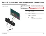
KDL-42W650A 7
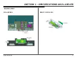
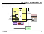
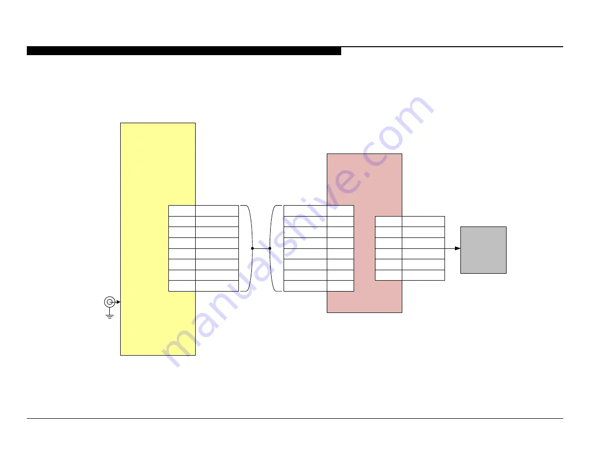
POWER AND CONTROL BLOCK DIAGRAM
19.5V
GND
PWM_DIMMER
1, 2
5
3, 4
VLED
LD_STBY
6
7
LD_MODE_SW
DC_DIMMER
8
9
CN8202
CN1001
LD
BLX
10
LD_ERR
1
3
4
5
6
7, 8
9, 10
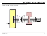
IP_REF
LD_MODE_SW
LD_STBY
FB_REF
PWM
VCC_IN
GND
LD_ERR
2
DC IN
LED 1
LED 2
LED 3
1
3
2
LED 4
NC
4
5 ~ 10
LED_VCC
11 ~ 14
LED
BACKLIGHTS
MAIN BOARD
LOCAL DIMMING


