1-15
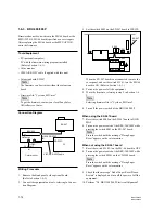
BRC-300/300P
BRU-300/300P
VISCA RS-232C IN
VISCA RS-232C
cable
PC
RS-232C
RM-BR300
1-6-4. RM-BR300
Firmware has not been written in the MC-66 board or the
MPU (IC5004/MD-131 board) specified as a service part.
After replacing the MD-131 board or the MPU (IC5004),
write the firmware.
Equipment/Tools
.
PC (Personal computer)
PC with the firmware writing program installed
(Refer to Section 1-6-1.)
.
VISCA RS-232C cable (Supplied with this unit)
.
Firmware file: “controlier.mot”
n
To get the firmware, please contact your local Sony
Sales Office/Service Center.
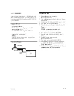
Connection Diagram
Writing Procedure
1.
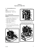
Remove the outer (upper) assembly.
(Refer to Section 1-5-1.)
2.
Connect the equipment and tools, referring to Connec-
tion Diagram.
3.
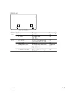
Set the switch S5006-2 on the MD-131 board to ON.
4.
Turn on the power of each equipment.
5.
Write the firmware, referring to step 5 in Section 1-6-
2.
n
Selecting firmware file is “controller.mot”.
6.
Turn off the power switch of the RM-BR300.
7.
Reset the switch S5006-2 on the MD-131 board to
OFF.
8.
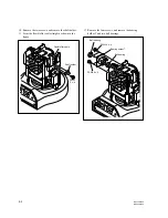
Reattach the outer (upper) assembly.
(Refer to Section 1-5-1.)
9.
Turn on the power switch of the RM-BR300.
10. Press the MENU button for two seconds while press-
ing the RESET, PRESET, and L/R DIRECTION
buttons simultaneously.
11. Check that the blinking speed of the indicator changes,
and turn off the power of each equipment.

