(5-7-6. R L-12 Board)
5. SiT
Reels and Timer Roller Rotational
Direction Detection
and
reels Rotational
Detection
The REEL FG signals corresponding
to the reel rotational
speed are input into the RL borad via the FG amplifier on the
RA board, and
are converted into
TTL level
the first
stage comparator.
The converted REEL FG A and B signals are
made the clock
with
double that of the FG
ICIC (EXCLUSIVE
OR) and these are counted by IC21 (CTC).
Based on these count data, the rotational
speed is detected by
the CPU.
The S-reel FG pulses are counted by IC21-9 while the T-reel FG
pulses are counted
IC21-IS.
Timer Roller Rotational
Detection
with the reels,
roller rotational
detected
using the phase difference of the TIMER FG A and B signals.
The TIMER FG A and B signals, input into the RL board via
the FG amplifier on the TT board, are converted into the TTL
level by the comparator
IC1. The converted TIMER FG A and
svncnromzeo
with 0.8
IC I D
and, along with the CTL pulses from the CD board which are
synchronized
by ICI D at the same time, they are input into
with double the rrequencv
FG signals are output from ICIE-II
(PROM), the addressing
noise of the PROM included in the output
is eliminated
by ICIF and the pulses are counted by IC21-I8 (CTC). Based on
these count data, rotational speed of timer roller is detected by
CPU.
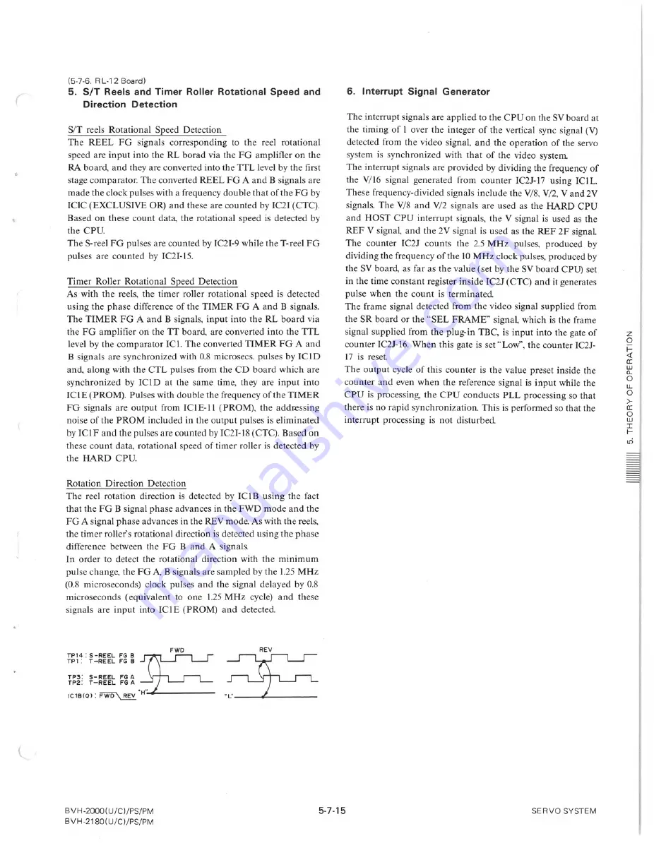
The reel rotation direction is detected
ICI B using the fact
that the FG B signal phase advances in the FWD mode and the
A
advances in the REV mode. As
the
the timer roller's rotational direction is detected using the phase
difference between the FG B and A signals.
In order to detect the rotational
direction with the minimum
pulse change, the FG
A,
B signals are sampled by the 1.25 MHz
and the
microseconds
(equivalent
to one 1.25 MHz cycle) and these
signals are input into ICI E (PROM)
and detected
: S-REEL
FG 8
T-REEL
FG 8
REV
.
TP3:
S- REEL
FG A
TP2:
T-REEL
FG A
IC1B(Q):
FWD \ REV
BVH-2000(U/C)/PS/PM
BVH-2180( U/C)/PS/PM
6. Interrupt
Generator
The interrupt signals are applied to the CPU on the SV board at
the
of
the
vertical
detected from the video signal, and the operation
of the servo
system is synchronized
with that of the video system.
The
are provided
dividing the frequency of
the V/16 signal generated
from counter
IC2l-I7 using ICI L.
These
the V/8, V/2, V
signals. The V/8 and V/2 signals are used as the HARD CPU
and HOST CPU interrupt
signals, the V signal is used as the
and the
is used as the REF 2F
The counter
IC2l counts
the 2.5 MHz pulses, produced
by
dividinz the
of the 10 MHz clock
the SV board, as far as the value (set by the SV board CPU) set
in the time constant register inside IC2l (CTC) and it generates
the count
The frame signal detected from the video signal supplied from
the SR board or the "SEL FRAME" signal, which is the frame
signal supplied from the plug-in TBC, is input into the gate of
counter IC2l-16. When this gate is set "Low", the counter IC2l-
17
The output cycle of this counter is the value preset inside the
counter and even when the reference signal is input while the
CPU is
the
conducts
PLL processing
that
there is no rapid synchronization.
This is performed so that the
1~t,ClIrrltl,....t
pr()Ce~;SUH!is not disturbed
5-7-1
SERVO SYSTEM
Summary of Contents for BVH-2000
Page 1: ...he handles available panels are optional Iy ...
Page 4: ......
Page 11: ......
Page 43: ......
Page 45: ......
Page 46: ......
Page 73: ......
Page 87: ......
Page 91: ......
Page 92: ......
Page 105: ......
Page 106: ......
Page 114: ......
Page 117: ......
Page 118: ......
Page 119: ......
Page 120: ......
Page 121: ......
Page 122: ......
Page 123: ......
Page 124: ......
Page 139: ......
Page 141: ......
Page 149: ......
Page 150: ......
Page 155: ......
Page 161: ......
Page 163: ......
Page 179: ......
Page 181: ...ARM 1 C C C ilr l I ...
Page 185: ......
Page 191: ......
Page 195: ......
Page 201: ......
Page 203: ......
Page 219: ......
Page 221: ......
Page 223: ......
Page 224: ......
Page 225: ......
Page 226: ......
Page 227: ......
Page 228: ......
Page 229: ......
Page 239: ......
Page 245: ......
Page 250: ...z o i a o LL Z BVH 2000 U C PS PM BVH 2180 U C PS PM ...
Page 257: ......
Page 259: ......
Page 265: ......
Page 269: ......
Page 305: ......
Page 323: ......
Page 344: ......
Page 370: ...15 ...
Page 371: ......
Page 375: ......
Page 388: ...of Standard Load for Output Check POWER UNIT 1 Standard for Variable a w o a 0 ...
Page 396: ...CN921 8 1 Spec CN921 8 5 Spec hoard BVH 2000 U C PS PM BVH 2500 U C P on ON 100 OFF 5 ...
Page 401: ......
Page 435: ......
Page 449: ......
Page 452: ......
Page 462: ......
Page 471: ......
Page 476: ......
Page 480: ......
Page 482: ... o w o ...
Page 484: ......
Page 492: ......
Page 494: ...80 U C ...
Page 496: ......
Page 497: ......
Page 498: ...14 2 BVH 2000 U C PS PM BVH 2500 U C P 80 U C PS PM w l j j Capstan Ree Servo Check ...
Page 500: ...lel pin 3 12 0 01 Vdc RVl TP5 EQ 02 NG Edge Can nectar Pin 21 B A B R138 w I U U ...
Page 504: ......
Page 505: ...BVH 2000 U C 3 673 996 22 Volume 1 1985 Printed in Japan 1985 4 09 ...


