Sony BVM-E250, Operation Manual
The Sony BVM-E250 is a high-performance monitor designed for professional use. With impressive specifications including a 25-inch OLED display and unmatched color accuracy, this monitor ensures a superb viewing experience. Download the user manual for free at 88.208.23.73:8080 to unlock all the features and settings of this exceptional product.
Share
Download

Reviews:
No comments
Related manuals for BVM-E250

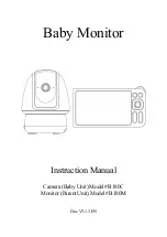
8232
Brand: Safety 1st Pages: 22

DCS-825L
Brand: D-Link Pages: 24
B180C
Brand: GardePro Pages: 49

DCS-855L
Brand: D-Link Pages: 16

DCS-700L
Brand: D-Link Pages: 16

DCS-850L
Brand: D-Link Pages: 32

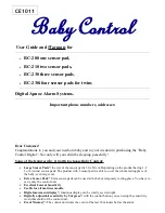
BC-200
Brand: Baby Control Digital Pages: 16
BC-200
Brand: Baby Control Digital Pages: 12
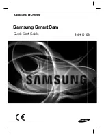
SmartCam SNH-1010N
Brand: Samsung Pages: 20

BrilliantVIEW SEW-3041W
Brand: Samsung Pages: 9
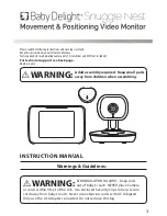
SNUGGLE NEST
Brand: BABY DELIGHT Pages: 12

YOO Master 3.5
Brand: babymoov Pages: 48
Yoo-Travel
Brand: babymoov Pages: 2

Premium Care
Brand: babymoov Pages: 40

A014409
Brand: babymoov Pages: 2

BC-100
Brand: Hama Pages: 51

SENSORSAFE
Brand: gb PLATINUM Pages: 72
Baby Control BC-439
Brand: Hama Pages: 20


