1-15 (E)
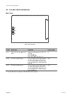
BVP-900 P1
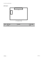
MD-83 board
Ref. No.
Switch name
Description
Factory setting
S1
R ON/OFF switch
Select the combination of R, G and B
All ON
S2
G ON/OFF switch
signals input to the Y, R-Y and B-Y matrix
S3
B ON/OFF switch
circuits for board adjustment.
*
2
S4
PROMPTER DIRECTION select
Selects the direction of the prompter signal
CCU
→
CAM
switch
to be transmitted between the camera and
CCU.
CCU
→
CAM: The prompter signal is
transmitted from the CCU
to the camera and then it is
output at the PROMPTER
connector of the camera.
CAM
→
CCU: The prompter signal is input
at the PROMPTER connector
of the camera and then it is
transmitted to the CCU.
*
2
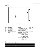
Adjusting point
S1
S2
S3
RV101 (Y REF)
ON
ON
ON
RV201 (R-Y REF)
OFF
ON
ON
RV301 (B-Y REF)
OFF
OFF
ON
12
11
10
9
8
7
6
5
4
3
2
1
R
Q
P
N
M
L
K
J
H
G
F
E
D
C
B
A
S4
S1
S2
S3
MD-83 BOARD (A SIDE)
1-8. Function of Internal Switches
Summary of Contents for BVP-900 Series
Page 4: ......
Page 30: ......
Page 36: ......
Page 160: ......
Page 167: ......
Page 181: ......
Page 193: ......
Page 224: ......
Page 272: ......
Page 275: ......
Page 278: ......
Page 282: ......
Page 363: ......
Page 384: ......
Page 396: ......
Page 404: ......
Page 408: ......
Page 411: ......
Page 412: ......
Page 414: ......
Page 454: ......
Page 455: ......
Page 479: ......
Page 480: ......
Page 482: ......
Page 498: ......
Page 519: ......
Page 520: ......

