5 (E)
Functions of the Routing
Switcher System
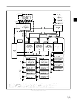
The routing switcher system is equipped with the
following functions.
Designated input and output line protect
function
This function prohibits the switching of protected
output signals from other control panels (protect
function) and protects the designated crosspoints by
hiding the input signals from all control panels and in
turn prohibiting switching from other control panels
(secret function).
Phantom function
You can switch several crosspoints at the same time.
Self-diagnosis function
You can send and display information about whether
an error has occurred or not to the terminal connected
to the primary station.
When you designate the DVS-V3232B or DVS-
V6464B as a primary station, and the BVS-A3232 as a
secondary station, following functions will be
available.
Crosspoint disable function
For every output signal, you can limit the input signals
available for selection so that any particular input
signals can be output to the specified output lines.
Password function
You can enter a password to prevent unauthorized
users from accessing the system.
Name setting function
You can set names for each input and output connector
in order to distinguish among the connected signals.
Two methods are available for setting the names;
either enter the device name and number (i.e. name of
the VTR, camera, etc.), for example VTR 1, or a
description using up to 16 characters. You can display
the name on the optional BKS-R3280/R3281 display
unit and BKS-R3202/R3205/R3206 control units.
Virtual mapping function
You can set crosspoints on a virtual matrix.
Free assignment function
You can assign a different connector number to a
connector name on each level.
Tie line function
You can enable the system to automatically select the
signal line that connects two or three routing switchers.
Features of an S-BUS System
An S-BUS control system transmits the control signals
among several routing switchers and control units that
are connected with one coaxial cable. In an S-BUS
control system, one switcher is designated as the
primary station which controls the entire system, and
the remaining switchers and control units are
designated as secondary stations. Signal transmission
between the secondary stations is controlled by the
primary station.
The S-BUS control system has the following features.
•
LAN (Local Area Network) type control signal
transmission using a single 75-ohm coaxial cable.
•
Possible extension of the coaxial cable up to 500
meters when a BELDEN 8281 or equivalent cable is
used.
•
Possible connection and disconnection of a switcher
or control unit to the S-BUS line during normal
operations without turning the power off.
•
Control of multiple S-BUS lines and up to 254
switchers and control units (including the primary
station) from the routing switcher designated as the
primary station.
•
Possible connection of a maximum of 128 routing
switchers and control units to one S-BUS line.
•
Display of the errors detected through the self-
diagnosis function on the terminal connected to the
primary station on the S-BUS line.
•
Ten year storage of the settings made with the
terminal (system settings and table data) and the
crosspoint data in either the memory of the primary
or secondary stations.


