6-1
BVW-55
Section 6
Circuit Description and Overall Block Diagram
The following block diagrams are provided after the circuit description.
.
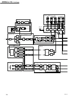
Overall (1/3) : Signal Processing System ........................................... 6-4
.
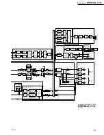
Overall (2/3) : System Control & Servo Control System(1/2) ........... 6-6
.
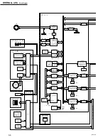
Overall (3/3) : System Control & Servo Control System (2/2) .......... 6-8
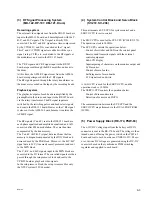
The digital component video signal output from the video
process IC is divided into two lines by the composite
encode IC, where one is encoded to the digital composite
video signals, and the other is input to the SDI-23 board
and scan converter IC.
The digital composite video signal output from the com-
posite encode IC is D/A converted, and output from the
connector panel (CP-317 board). There are two outputs;
Characters can be superimposed to the VIDEO OUTPUT
2.
The digital component video signal sent to the SDI-23
board is multiplexed with the audio signal, parallel/serial
converted, and output from the connector panel.
The scan converted signal is further D/A converted, and
subject to RGB signal conversion, and gain adjustment in
the DP-300 board, and then sent to the color LCD monitor
(VGA 640
x
480).
Sync system
Reference internal signals for the video and audio systems
are produced in the TG-191 board.
Either the reference video signal input to the REF.VIDEO
connector or the video signal input to the VIDEO IN
connector is sent to the timing generation block on the TG-
191 board from the CP-317 board.
In the timing generation block, sync and burst signals are
separated and extracted from the input video signal.
Sync signals (HD, VD, and CF) are extracted from the SDI
signal input to the SDI INPUT connector by the SDI
decode block on the SDI-23 board.
On the TG-191 board, reference internal signals, timing
signals (HD, VD, FRAME, and CF), and clocks (for video
and audio) synchronized with this reference signal are
produced based on the extracted sync signals. These
signals and clocks are then sent to each board.
The reference signal (SV REF) for the servo system is also
produced by the timing generation block on the TG-191
board and sent to the SV-206 board.
(1) Video Signal Processing System
(CP-317, DEC-97, SDI-23, VPR-59,
DP-300, TG-191)
Recording system
The analog composite video signal input from the VIDEO
INPUT connector is sent from the CP-317 board to the
DEC-97 board, A/D converted, converted to the digital
component signal (parallel) by the composite decode
block. This digital component signal is sent to the input
TBC block on the SDI-23 board.
The SDI signal input from the SDI INPUT connector is
input to the SDI-23 board, serial/parallel converted, the
SDI video signal is extracted at the D1 decode block.
(The SDI audio signal is extracted at the audio Rx TBC
block.)
This SDI video signal is also sent to the input TBC block
on the SDI-23 board.
The input TBC block on the SDI-23 board synchronizes
the input video signal (SDI video signal or digital compo-
nent signal from the DEC-97 board) with the reference
block inside this unit.
The input video signal output from the input TBC block is
sent to the MD-122 board as REC data via the setup
remove and VITC generation blocks.
The VITC generation block reads the VITC and sets data
for recording.
The REC data is also sent to the VPR-59 board as EE data
(Input E-E video signal).
Playback system
In the VPR-59 board, either the playback video signal sent
from the DM-121 board or the input EE video signal sent
from the SDI-23 board is selected by video process IC,
after which video process (gain adjustment, setup adjust-
ment, addition of blanking, etc.) is performed.
Summary of Contents for BVW-55
Page 4: ......
Page 8: ......
Page 50: ...1 40 BVW 55 1 2 3 4 5 6 7 8 9 d l s d l 1 15 Fixtures and Adjustment Equipment List ...
Page 58: ......
Page 106: ......
Page 116: ......
Page 130: ......
Page 148: ......
Page 154: ......
Page 158: ......
Page 169: ...1 9 BVW 55 P2 1 2 Fixtures and Adjustment Equipment List 1 2 3 4 5 6 7 8 9 d l s d l ...
Page 176: ......
Page 272: ......
Page 384: ......
Page 392: ......
Page 396: ...1 2 BVW 55 ...
Page 666: ......
Page 705: ......
Page 752: ......
Page 780: ......
Page 805: ......
Page 848: ......
Page 856: ......
Page 870: ......
Page 884: ......
Page 904: ......
Page 909: ...5 27 b BVW 55 5 27 b CN101 CN301 CN302 CN303 CN901 MB 838 B SIDE SUFFIX 12 MB 838 MB 838 ...
Page 911: ...5 27 a BVW 55 5 27 a CN101 CN301 CN302 CN303 CN901 MB 838 B SIDE SUFFIX 11 MB 838 MB 838 ...
Page 940: ......


