1-4
BVW-55 P2
DR2-RP6
SR66-RP6
DR1-RP
C
PWH2.6
x
5
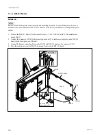
Acoustic isolation plate
RP-107 board
Drum assembly
Chassis
Acoustic isolation plate
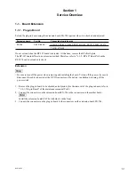
1-1. Board Extension
Installation
1.
Remove the RP-107 board, extension board and extension harnesses in the reverse order of steps 3 to
6 in “Extension”.
2.
Temporarily attach the RP-107 board to the acoustic isolation plate with the two screws (
C
PWH2.6
x
5).
3.
Connect the three harnesses (DR1-RP, DR2-RP6 and SR66-RP6) to the drum assembly.
4.
Lightly insert the RP-107 board. At this time, insert the acoustic isolation plate into the position
shown in the figure.
n
Take care not to catch the harnesses between the acoustic isolation plate and the chassis.
Summary of Contents for BVW-55
Page 4: ......
Page 8: ......
Page 50: ...1 40 BVW 55 1 2 3 4 5 6 7 8 9 d l s d l 1 15 Fixtures and Adjustment Equipment List ...
Page 58: ......
Page 106: ......
Page 116: ......
Page 130: ......
Page 148: ......
Page 154: ......
Page 158: ......
Page 169: ...1 9 BVW 55 P2 1 2 Fixtures and Adjustment Equipment List 1 2 3 4 5 6 7 8 9 d l s d l ...
Page 176: ......
Page 272: ......
Page 384: ......
Page 392: ......
Page 396: ...1 2 BVW 55 ...
Page 666: ......
Page 705: ......
Page 752: ......
Page 780: ......
Page 805: ......
Page 848: ......
Page 856: ......
Page 870: ......
Page 884: ......
Page 904: ......
Page 909: ...5 27 b BVW 55 5 27 b CN101 CN301 CN302 CN303 CN901 MB 838 B SIDE SUFFIX 12 MB 838 MB 838 ...
Page 911: ...5 27 a BVW 55 5 27 a CN101 CN301 CN302 CN303 CN901 MB 838 B SIDE SUFFIX 11 MB 838 MB 838 ...
Page 940: ......


