2-20
BVW-55 P2
NO OPERA TION
0
0
LCD monitor
Sub LCD
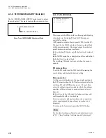
A1F:NV-RAM CONTROL
NO OPERATION
SAVE ALL ADJUST DATA
ALL DATA PREVIOUS
*
*
(1)
0
DIAL (
2
)
SAVE ALL ADJUST
A1F:NV-RAM CONTROL
NO OPERATION
SAVE ALL ADJUST DATA
ALL DATA PREVIOU
(2)
0
[SET]
SAVING
A1F:NV-RAM CONTROL
Saving ..
0
Confirm
[MENU]
SAVE CO MPLETE
A1F:NV-RAM CONTROL
Save Complete
(3)
(4)
A1F : NV-RAM CONTROL
The A1F : NV-RAM CONTROL menu is used to save the
recording system adjustment data adjusted in the BETA-
CAM REC ADJUST mode in NV-RAM.
The current adjustment data can return to the former state
when “ALL DATA PREVIOUS” is selected before the
adjustment data is saved in NV-RAM.
m
.
Do not save the adjustment data in NV-RAM when
abnormality is found during automatic adjustment (when
message “Auto Adjust Failure” or “Condition NG” is
displayed).
.
When the adjustment data was not stored in this menu, it
returns to the state before adjustment if the power is
turned off.
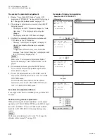
To execute the menu
(1) Turn the JOG dial and move the
*
mark on the LCD
monitor as described below.
To save the adjustment data after adjustment:
8
“SAVE ALL ADJUST DATA”
To return to the adjustment data before adjustment
8
“ALL DATA PREVIOUS”
.
In a sub LCD, “SAVE ALL ADJUST DATA” and
“ALL DATA PREVIOUS” are displayed as
messages “SAVE ALL ADJUST” and “ALL
DATA PREVIOUS”, respectively.
(2) Press the SET button.
.
The data transmission is initiated when the SET
button is pressed.
.
Message “Saving ...” or “Loading ...” is displayed
on the LCD monitor, and message
“SAVING” or “LOADING” is displayed in the sub
LCD.
(3) Confirm that the data transmission is completed.
.
After data transmission is completed, message
“Save Complete” or “Load Complete” is displayed
on the LCD monitor, and message “SAVE COM-
PLETE” or “LOAD COMPLETE” is displayed in
the sub LCD.
(4) Press the MENU button to terminate the menu.
Example of display and operation
(In data save)
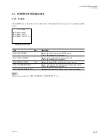
2-2. TAPE Maintenance Mode (M0)
2-2-3. BETACAM REC ADJUST Mode (A1)
Summary of Contents for BVW-55
Page 4: ......
Page 8: ......
Page 50: ...1 40 BVW 55 1 2 3 4 5 6 7 8 9 d l s d l 1 15 Fixtures and Adjustment Equipment List ...
Page 58: ......
Page 106: ......
Page 116: ......
Page 130: ......
Page 148: ......
Page 154: ......
Page 158: ......
Page 169: ...1 9 BVW 55 P2 1 2 Fixtures and Adjustment Equipment List 1 2 3 4 5 6 7 8 9 d l s d l ...
Page 176: ......
Page 272: ......
Page 384: ......
Page 392: ......
Page 396: ...1 2 BVW 55 ...
Page 666: ......
Page 705: ......
Page 752: ......
Page 780: ......
Page 805: ......
Page 848: ......
Page 856: ......
Page 870: ......
Page 884: ......
Page 904: ......
Page 909: ...5 27 b BVW 55 5 27 b CN101 CN301 CN302 CN303 CN901 MB 838 B SIDE SUFFIX 12 MB 838 MB 838 ...
Page 911: ...5 27 a BVW 55 5 27 a CN101 CN301 CN302 CN303 CN901 MB 838 B SIDE SUFFIX 11 MB 838 MB 838 ...
Page 940: ......


