2-21
BVW-55 P2
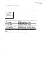
A2 : AUDIO/VIDEO ADJUST
A20 : VPR/TG VR
A23 : SDI VR
A231 : SDI ENC VCO
A232 : SDI DEC VCO
A24 : INPUT CF DETECT
A25 : DEC VR
A26 : DEC VR (LOOP)
A27 : VIDEO METER
A2F : NV-RAM CONTROL
2-2-4. AUDIO/VIDEO ADJUST Mode (A2)
The A2 : AUDIO/VIDEO ADJUST mode is used to adjust
the audio and video systems.
This unit has seven menus.
In A23 : SDI VR menu, two submenus.
Menu Tree of Audio/Video Systems Adjustment Mode
c
Do not change the adjustment data carelessly. This may
cause a trouble. For the actual adjustment, refer to the
adjustment method described in Section 7.
If you have changed the adjustment data carelessly,
execute ALL DATA PREVIOUS in an A2F : NV-RAM
CONTROL menu or turn off the power of this unit without
selecting an A2F : NV-RAM CONTROL menu.
Never execute SAVE ALL ADJUST DATA.
The adjustment menus other than submenus of A23 and
menu A24 are used for manual adjustment.
In the submenus of A23 and menu A24, automatic adjust-
ment (AUTO) or manual adjustment (MANUAL) can be
selected.
For the automatic adjustment, refer to the operation
example described in each menu.
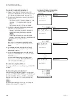
To change the adjustment data manually
(1) Turn the JOG dial on the LCD monitor and move the
*
mark to the item to be adjusted.
Turn the JOG dial in the sub LCD and display the item
to be adjusted.
(2) Turn the JOG dial while pressing the search button.
The adjustment data then increases or decreases.
To execute the automatic adjustment
(1) Turn the JOG dial on the LCD monitor and move the
*
mark to “MANUAL”.
Turn the JOG dial in the sub LCD and display “MAN-
UAL”.
(2) Turn the JOG dial in FORWARD (
2
) direction while
pressing the search button. Message “Auto (Push SET
Button)” is then displayed on the LCD monitor, and
message “PUSH SET” is displayed in the sub LCD.
(3) The automatic adjustment is executed when the SET
button is pressed.
.
Only the display on the LCD monitor changes as
described below. The displayed data value also
changes.
Auto adjusting .. :
Automatic adjustment is in
progress.
Auto Adjust Complete : Automatic adjustment is
completed.
Auto Adjust Failure :
Automatic adjustment
fails.
To return the adjustment data to the former state
Execute ALL DATA PREVIOUS in an A2F : NV-RAM
CONTROL menu.
n
The current adjustment data can not return to the former
state after executing SAVE ALL DATA ADJUST DATA.
2-2. TAPE Maintenance Mode (M0)
2-2-4. AUDIO/VIDEO ADJUST Mode (A2)
Summary of Contents for BVW-55
Page 4: ......
Page 8: ......
Page 50: ...1 40 BVW 55 1 2 3 4 5 6 7 8 9 d l s d l 1 15 Fixtures and Adjustment Equipment List ...
Page 58: ......
Page 106: ......
Page 116: ......
Page 130: ......
Page 148: ......
Page 154: ......
Page 158: ......
Page 169: ...1 9 BVW 55 P2 1 2 Fixtures and Adjustment Equipment List 1 2 3 4 5 6 7 8 9 d l s d l ...
Page 176: ......
Page 272: ......
Page 384: ......
Page 392: ......
Page 396: ...1 2 BVW 55 ...
Page 666: ......
Page 705: ......
Page 752: ......
Page 780: ......
Page 805: ......
Page 848: ......
Page 856: ......
Page 870: ......
Page 884: ......
Page 904: ......
Page 909: ...5 27 b BVW 55 5 27 b CN101 CN301 CN302 CN303 CN901 MB 838 B SIDE SUFFIX 12 MB 838 MB 838 ...
Page 911: ...5 27 a BVW 55 5 27 a CN101 CN301 CN302 CN303 CN901 MB 838 B SIDE SUFFIX 11 MB 838 MB 838 ...
Page 940: ......


