2-27
BVW-55 P2
AUDIO/VIDEO ADJUST MODE
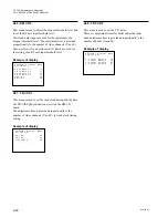
A27:VIDEO METER
Manual
VIDEO METER A9
LEVEL 0
*
1
2
3
AUDIO/VIDEO ADJUST MODE
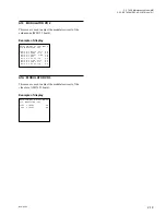
A26:DEC VR (LOOP)
VIDEO GAIN 80
*
AUDIO/VIDEO ADJUST MODE
A25:DEC VR
VIDEO GAIN 80
PEDESTAL 00
*
A25 : DEC VR
This menu is used to adjust the composite video input
system.
n
This adjustment is necessary to perform both 525/60 and
625/50 systems.
Adjustment item
Description
VIDEO GAIN
Composite video input level
PEDESTAL
Composite video input pedestal clamp level
n
The adjustment data in an A25 : DEC VR menu is used in
common with the same adjustment item in an A26 : DEC
VR (LOOP) menu.
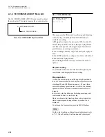
A26 : DEC VR (LOOP)
This menu is used to adjust the composite video input
system.
The most suitable signal (refer to the table below) for
adjustment is output from an internal video test signal
generator, and the composite video input system can be
adjusted with the multi-loop function activated.
n
This adjustment is necessary to perform both 525/60 and
625/50 systems.
Adjustment item
Test signal
VIDEO GAIN
100% Color Bars
n
The adjustment data in an A26 : DEC VR (LOOP) menu is
used in common with the same adjustment item in an A25 :
DEC VR menu.
A27 :VIDEO METER
This menu is used for the calibration of video meter on the
sub LCD.
Before adjustment, inputs the reference video signal to the
VIDEO INPUT connector on the rear panel, and set the
unit into the EE mode.
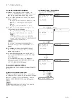
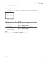
Description of LCD monitor
1
The adjustment mode (manual and automatic adjust-
ments) or the messages during automatic adjustment
are displayed in this line.
Manual :
Adjustment mode is set to
the manual adjustment.
Auto (Push SET Button): Press the SET button to
initiate the automatic
adjustment.
Auto Adjusting ... :
Automatic adjustment is in
progress.
Auto adjust Complete :
Automatic adjustment is
completed.
Auto Adjust Failure :
Automatic adjustment fails.
n
The adjustment data can be manually changed even if
message “Auto (Push SET Button)” is displayed.
2
The adjustment item and adjustment data value are
displayed in this line.
3
When the reference video signel is not input, the
message “LEVEL 0” is displayed.
2-2. TAPE Maintenance Mode (M0)
2-2-4. AUDIO/VIDEO ADJUST Mode (A2)
Summary of Contents for BVW-55
Page 4: ......
Page 8: ......
Page 50: ...1 40 BVW 55 1 2 3 4 5 6 7 8 9 d l s d l 1 15 Fixtures and Adjustment Equipment List ...
Page 58: ......
Page 106: ......
Page 116: ......
Page 130: ......
Page 148: ......
Page 154: ......
Page 158: ......
Page 169: ...1 9 BVW 55 P2 1 2 Fixtures and Adjustment Equipment List 1 2 3 4 5 6 7 8 9 d l s d l ...
Page 176: ......
Page 272: ......
Page 384: ......
Page 392: ......
Page 396: ...1 2 BVW 55 ...
Page 666: ......
Page 705: ......
Page 752: ......
Page 780: ......
Page 805: ......
Page 848: ......
Page 856: ......
Page 870: ......
Page 884: ......
Page 904: ......
Page 909: ...5 27 b BVW 55 5 27 b CN101 CN301 CN302 CN303 CN901 MB 838 B SIDE SUFFIX 12 MB 838 MB 838 ...
Page 911: ...5 27 a BVW 55 5 27 a CN101 CN301 CN302 CN303 CN901 MB 838 B SIDE SUFFIX 11 MB 838 MB 838 ...
Page 940: ......


