2-28
BVW-55 P2
MANUAL
0
0
0
0
LCD monitor
Sub LCD
(1)
0
[Search]
+
DIAL(
2
)
PUSH SET
(2)
0
[SET]
PUSH SET
0
(omitted)
0
Confirm
[MENU]
[MENU]
Data save
PUSH SET
(3)
(4)
(5)
*
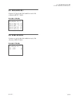
A2F:NV-RAM CONTROL
AUDIO/VIDEO ADJUST MODE
A27:VIDEO METER
Manual
VIDEO METER A9
*
*
*
*
AUDIO/VIDEO ADJUST MODE
A27:VIDEO METER
Auto(Push SET button)
VIDEO METER A9
AUDIO/VIDEO ADJUST MODE
A27:VIDEO METER
Auto Adjusting...
VIDEO METER 00
AUDIO/VIDEO ADJUST MODE
A27:VIDEO METER
Auto Adjust Complete
VIDEO METER A5
COND
TC
VITC
LTC
525
SX 60
BATT
01 : 23 : 45 : 01
AU 1
LTC
VITC ON
SDI
F1
PAGE
F2
F3
F4
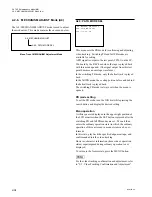
Video meter
Sub LCD
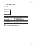
Example of display and operation
Change of adjustment mode
The relation between the adjustment mode and display is
shown in the table below.
Adj. mode
LCD monitor
Sub LCD
Manual adjustment
Manual
MANUAL
Automatically adjustable Auto (Push SET Button)
PUSH SET
(i) Turn the JOG dial in REVERSE (
3
) direction and
move the
*
mark to line
1
on the LCD monitor. (In a
sub LCD, “MANUAL” or “PUSH SET” is displayed.)
(ii) Turn the JOG dial while pressing the search button.
Manual
8
Automatic:
[Search]
+
DIAL (
2
)
Manual
7
Automatic:
[Search]
+
DIAL (
3
)
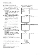
To execute the automatic adjustment
(1) Display “Auto (Push SET Button)” on the LCD
monitor and “PUSH SET” in the sub LCD referring to
the “Change of adjustment mode” described above.
(2) The automatic adjustment is executed when the SET
button is pressed.
.
The display on the LCD monitor changes to “Auto
Adjusting...”. The displayed data value also
changes.
The display in the sub LCD does not change.
(3) Confirm the automatic adjustment completion and
each status on the LCD monitor.
.
Message “Auto Adjust Complete” is displayed
when the automatic adjustment is completed.
n
If the preparation for adjustment is not proper, mes-
sage “Auto Adjust Failure” is displayed.
(4) To terminate the menu, press the MENU button.
To execute the automatic adjustment again in this
menu, return to step (2).
(5) To save the adjustment data in NV-RAM, execute
SAVE ALL ADJUST DATA in an A2F : NV-RAM
CONTROL menu.
To return the adjustment data to the state before
adjustment, execute ALL DATA PREVIOUS in an
A2F : NV-RAM CONTROL menu.
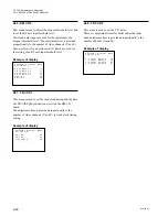
Caution during manual adjustment
Confirm the adjustment data range in which the display of
video meter is set to the intermediate value (five lines)
when performing the manual adjustment.
n
For the manual adjustment, refer to the “To change the
adjustment data manually” on page 2-21.
2-2. TAPE Maintenance Mode (M0)
2-2-4. AUDIO/VIDEO ADJUST Mode (A2)
Summary of Contents for BVW-55
Page 4: ......
Page 8: ......
Page 50: ...1 40 BVW 55 1 2 3 4 5 6 7 8 9 d l s d l 1 15 Fixtures and Adjustment Equipment List ...
Page 58: ......
Page 106: ......
Page 116: ......
Page 130: ......
Page 148: ......
Page 154: ......
Page 158: ......
Page 169: ...1 9 BVW 55 P2 1 2 Fixtures and Adjustment Equipment List 1 2 3 4 5 6 7 8 9 d l s d l ...
Page 176: ......
Page 272: ......
Page 384: ......
Page 392: ......
Page 396: ...1 2 BVW 55 ...
Page 666: ......
Page 705: ......
Page 752: ......
Page 780: ......
Page 805: ......
Page 848: ......
Page 856: ......
Page 870: ......
Page 884: ......
Page 904: ......
Page 909: ...5 27 b BVW 55 5 27 b CN101 CN301 CN302 CN303 CN901 MB 838 B SIDE SUFFIX 12 MB 838 MB 838 ...
Page 911: ...5 27 a BVW 55 5 27 a CN101 CN301 CN302 CN303 CN901 MB 838 B SIDE SUFFIX 11 MB 838 MB 838 ...
Page 940: ......


