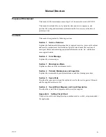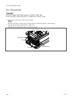
1-13
BVW-55
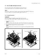
Harness
2
Harness
1
CN2
CN3
Battery sub panel
Battery sub panel
Shielding spring
CN-1662 board
Screws
Screws
1-6. Removing/Reinstalling the Cabinet
This section explains the removal and installation procedures for main parts.
For other mechanical parts, refer to the maintenance manual Part 2 Volume 1.
n
If two VTRs are coupled, remove the handle, joint plates and cables that are docking the VTRs in advance.
As for how to separate, refer to the operation manual supplied with the BVW-55.
1-6-1. Battery Sub Panel
c
The unit is equipped with shielding springs which have sharp edges.
Do not contact them with bare hands. Pay careful attention when servicing.
1.
Loosen the four screws fully.
n
Each screw is held by a stop washer. Do not separate the washer from the screw when loosening.
2.
Disconnect the two harnesses
1
and
2
from the connectors (CN2, CN3) on the CN-1662 board.
3.
Reinstall the battery sub panel in the reverse order of removal.
n
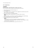
When reinstalling, take care that the harnesses are not caught between the upper frame and battery
sub panel.
1-6. Removing/Reinstalling the Cabinet
Summary of Contents for BVW-55
Page 4: ......
Page 8: ......
Page 50: ...1 40 BVW 55 1 2 3 4 5 6 7 8 9 d l s d l 1 15 Fixtures and Adjustment Equipment List ...
Page 58: ......
Page 106: ......
Page 116: ......
Page 130: ......
Page 148: ......
Page 154: ......
Page 158: ......
Page 169: ...1 9 BVW 55 P2 1 2 Fixtures and Adjustment Equipment List 1 2 3 4 5 6 7 8 9 d l s d l ...
Page 176: ......
Page 272: ......
Page 384: ......
Page 392: ......
Page 396: ...1 2 BVW 55 ...
Page 666: ......
Page 705: ......
Page 752: ......
Page 780: ......
Page 805: ......
Page 848: ......
Page 856: ......
Page 870: ......
Page 884: ......
Page 904: ......
Page 909: ...5 27 b BVW 55 5 27 b CN101 CN301 CN302 CN303 CN901 MB 838 B SIDE SUFFIX 12 MB 838 MB 838 ...
Page 911: ...5 27 a BVW 55 5 27 a CN101 CN301 CN302 CN303 CN901 MB 838 B SIDE SUFFIX 11 MB 838 MB 838 ...
Page 940: ......

