3-21
BVW-55 P2
P2
x
2
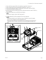
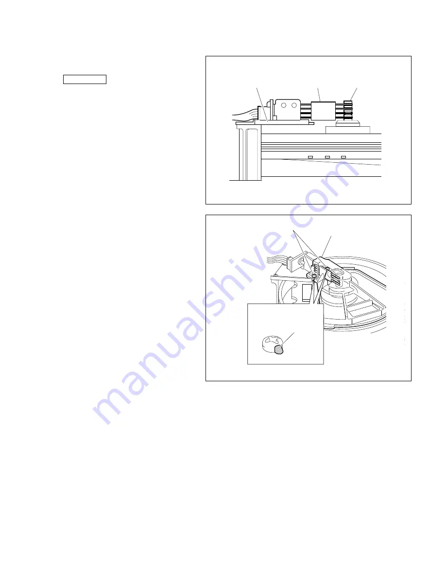
Brush cover
Locking compound
(5) Check that the brush surely touches the
grooves of the slip ring.
Reference
The brush height and the contact pressure to
the slip ring are automatically adjusted by
executing steps (1) to (3).
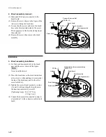
4. Brush cover installation
(1) Adjust the position so that the shaft of the slip
ring is almost located in the center of the hole
at the tip of the brush cover and fix the cover
with two screws.
[Tightening torque: 10
x
10
_
2
N
.
m
{1.0 kgf
.
cm}]
n
Be careful not to apply excessive force to the
brush base.
(2) Apply the screw locking compound to two
screws.
(3) Recheck that the brush surely touches the
grooves of the slip ring.
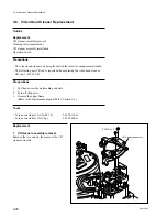
3-3. Brush Replacement
Brush base
Brush assembly
Slip ring assembly
Summary of Contents for BVW-55
Page 4: ......
Page 8: ......
Page 50: ...1 40 BVW 55 1 2 3 4 5 6 7 8 9 d l s d l 1 15 Fixtures and Adjustment Equipment List ...
Page 58: ......
Page 106: ......
Page 116: ......
Page 130: ......
Page 148: ......
Page 154: ......
Page 158: ......
Page 169: ...1 9 BVW 55 P2 1 2 Fixtures and Adjustment Equipment List 1 2 3 4 5 6 7 8 9 d l s d l ...
Page 176: ......
Page 272: ......
Page 384: ......
Page 392: ......
Page 396: ...1 2 BVW 55 ...
Page 666: ......
Page 705: ......
Page 752: ......
Page 780: ......
Page 805: ......
Page 848: ......
Page 856: ......
Page 870: ......
Page 884: ......
Page 904: ......
Page 909: ...5 27 b BVW 55 5 27 b CN101 CN301 CN302 CN303 CN901 MB 838 B SIDE SUFFIX 12 MB 838 MB 838 ...
Page 911: ...5 27 a BVW 55 5 27 a CN101 CN301 CN302 CN303 CN901 MB 838 B SIDE SUFFIX 11 MB 838 MB 838 ...
Page 940: ......


