3-24
BVW-55 P2
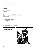
3-5. Drum Assembly Replacement
Outline
Replacement
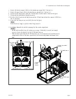
Drum assembly removal
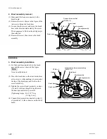
Installation surfaces cleaning
Drum assembly installation
Video heads and tape running surfaces cleaning
Adjustment after replacement
Tape running adjustment
Video tracking adjustment
CTL head position adjustment
AT head position adjustment
Drum phase system adjustment
PB system adjustment
REC system adjustment
Precaution
Be careful not to damage the CTL head, AT head, and peripheral tape guides when
replacing the drum assembly.
Take care that the video heads of the drum assembly is not damaged during re-
placement.
Basic knowledge
For except the periodic replacement, replace the drum assembly in the following cases.
.
When the damaged upper drum assembly or tape running surface cannot be
recovered
.
When no proper RF waveform can be obtained during tracking adjustment
because of the worn upper drum assembly or lower drum
.
When the VTR performance cannot be satisfied due to noises or jitters because of
its bearing life
Preparations
1.
Put the unit into the unthreading end state.
2.
Turn off the power.
3.
Remove the upper frame.
(Refer to the maintenance manual Part 1, Section 1-6.)
4.
Remove the cassette compartment.
(Refer to the maintenance manual Part 1, Section 1-7.)
Tools
.
Torque screwdriver bit (for M2):
J-6325-380-A
.
Torque screwdriver (for 3 kg):
J-6325-400-A
.
Cleaning cloth (15 cm
x
15 cm):
3-184-527-01
.
Cleaning liquid:
9-919-573-01
3-5. Drum Assembly Replacement
Summary of Contents for BVW-55
Page 4: ......
Page 8: ......
Page 50: ...1 40 BVW 55 1 2 3 4 5 6 7 8 9 d l s d l 1 15 Fixtures and Adjustment Equipment List ...
Page 58: ......
Page 106: ......
Page 116: ......
Page 130: ......
Page 148: ......
Page 154: ......
Page 158: ......
Page 169: ...1 9 BVW 55 P2 1 2 Fixtures and Adjustment Equipment List 1 2 3 4 5 6 7 8 9 d l s d l ...
Page 176: ......
Page 272: ......
Page 384: ......
Page 392: ......
Page 396: ...1 2 BVW 55 ...
Page 666: ......
Page 705: ......
Page 752: ......
Page 780: ......
Page 805: ......
Page 848: ......
Page 856: ......
Page 870: ......
Page 884: ......
Page 904: ......
Page 909: ...5 27 b BVW 55 5 27 b CN101 CN301 CN302 CN303 CN901 MB 838 B SIDE SUFFIX 12 MB 838 MB 838 ...
Page 911: ...5 27 a BVW 55 5 27 a CN101 CN301 CN302 CN303 CN901 MB 838 B SIDE SUFFIX 11 MB 838 MB 838 ...
Page 940: ......


