3-26
BVW-55 P2
Installation
2. Installation surfaces cleaning
Clean the installation surfaces of a new drum
assembly and chassis with cleaning cloth moist-
ened with cleaning fluid.
3. Drum assembly installation
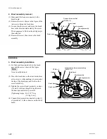
(1) Hold the new drum assembly and connect the
three connectors (CN1, CN2 and CN3)
disconnected in step (3) of procedure 1.
m
.
Be sure to hold the drum assembly portion
in which no video heads exist when
holding the new drum assembly.
.
Take care that the drum assembly does not
contact the CTL head, AT head, and
peripheral tape guides.
.
Do not apply excessive force to the brush.
(2) Connect the harness connector to the brush
board.
(3) Align the two positioning pins of the chassis
with the holes of the drum assembly, then
install.
(4) Confirm that the drum assembly is firmly
inserted into the positioning pins by moving
it slightly.
(5) Tighten the three screws.
[Tightening torque: 20
x
10
_
2
N
.
m
{2.0 kgf
.
cm}]
(6) Confirm that the brush surely touches the
grooves of the slip ring.
3-5. Drum Assembly Replacement
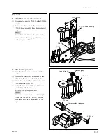
Positioning pins
Cleaning
Cleaning
Drum assembly
CN3
CN1
CN2
PS2
x
5
PS2
x
5
PS2
x
5
Harness
Video heads
Positioning pins
Summary of Contents for BVW-55
Page 4: ......
Page 8: ......
Page 50: ...1 40 BVW 55 1 2 3 4 5 6 7 8 9 d l s d l 1 15 Fixtures and Adjustment Equipment List ...
Page 58: ......
Page 106: ......
Page 116: ......
Page 130: ......
Page 148: ......
Page 154: ......
Page 158: ......
Page 169: ...1 9 BVW 55 P2 1 2 Fixtures and Adjustment Equipment List 1 2 3 4 5 6 7 8 9 d l s d l ...
Page 176: ......
Page 272: ......
Page 384: ......
Page 392: ......
Page 396: ...1 2 BVW 55 ...
Page 666: ......
Page 705: ......
Page 752: ......
Page 780: ......
Page 805: ......
Page 848: ......
Page 856: ......
Page 870: ......
Page 884: ......
Page 904: ......
Page 909: ...5 27 b BVW 55 5 27 b CN101 CN301 CN302 CN303 CN901 MB 838 B SIDE SUFFIX 12 MB 838 MB 838 ...
Page 911: ...5 27 a BVW 55 5 27 a CN101 CN301 CN302 CN303 CN901 MB 838 B SIDE SUFFIX 11 MB 838 MB 838 ...
Page 940: ......


