4-14
BVW-55 P2
3.0
±
0.1 mm
Precision
P2
x
2.2
Precision
P2
x
2.2
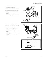
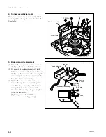
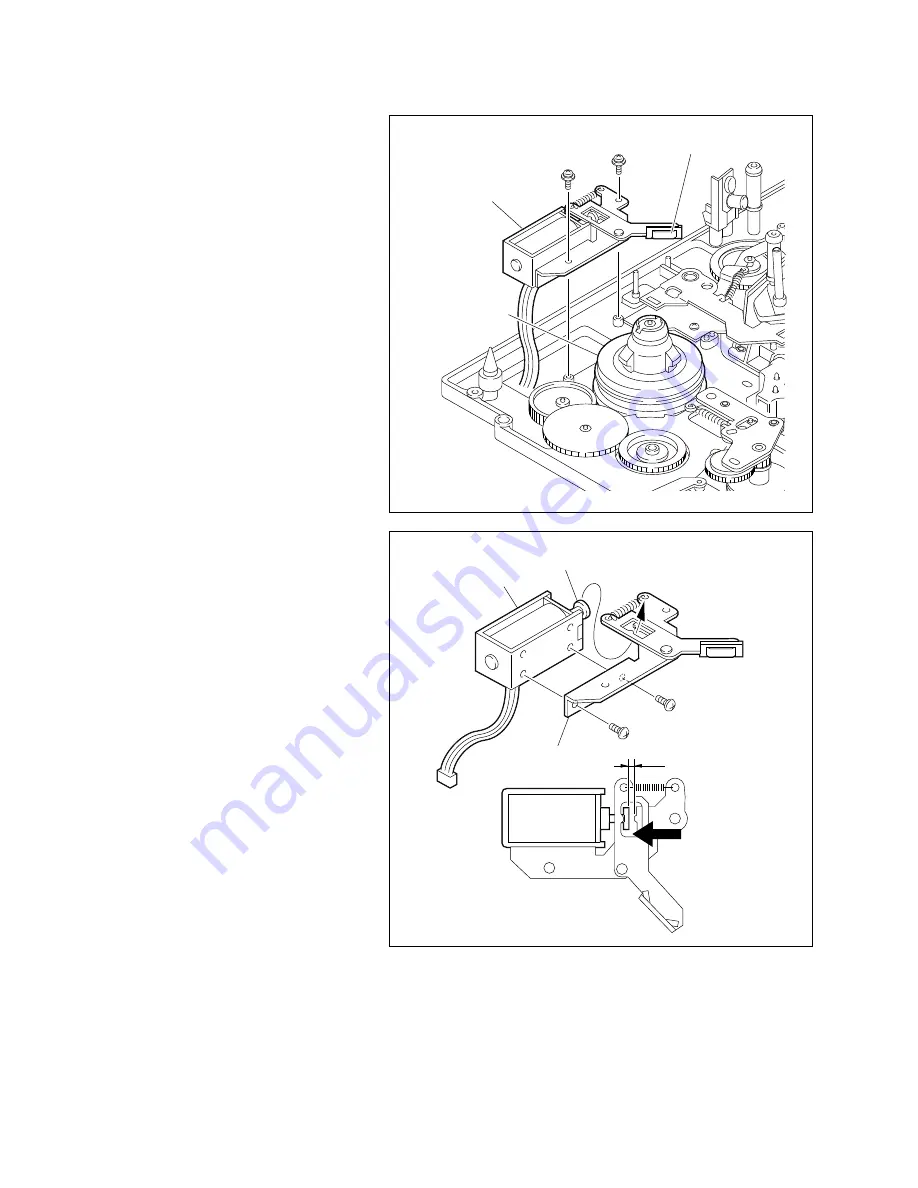
Brake solenoid
Push
Brake arm assembly
Iron core
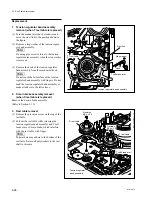
4. S brake assembly removal
Remove the two screws, then remove the S brake
assembly while releasing the brake shoe from the
S reel table.
5. Brake solenoid replacement
(1) Remove the two precision screws shown in
the figure, then remove the brake solenoid.
(2) Fix a new brake solenoid tentatively to the
brake arm assembly in the direction shown in
the figure with two screws while inserting the
iron core tip of a new brake solenoid into the
hole of the brake arm assembly.
(3) Position the brake solenoid so that the gap
between the tip of iron core and the protru-
sion of brake arm assembly is 3.0
±
0.1 mm
when pushing down the iron core in the
direction of the arrow by a finger and tighten
it with the two screws.
[Tightening torque: 20
x
10
_
2
N
.
m
{2.0 kgf
.
cm}]
4-4. S Brake Solenoid Replacement
PSW2
x
5
S brake assembly
S reel table
Brake shoe
Summary of Contents for BVW-55
Page 4: ......
Page 8: ......
Page 50: ...1 40 BVW 55 1 2 3 4 5 6 7 8 9 d l s d l 1 15 Fixtures and Adjustment Equipment List ...
Page 58: ......
Page 106: ......
Page 116: ......
Page 130: ......
Page 148: ......
Page 154: ......
Page 158: ......
Page 169: ...1 9 BVW 55 P2 1 2 Fixtures and Adjustment Equipment List 1 2 3 4 5 6 7 8 9 d l s d l ...
Page 176: ......
Page 272: ......
Page 384: ......
Page 392: ......
Page 396: ...1 2 BVW 55 ...
Page 666: ......
Page 705: ......
Page 752: ......
Page 780: ......
Page 805: ......
Page 848: ......
Page 856: ......
Page 870: ......
Page 884: ......
Page 904: ......
Page 909: ...5 27 b BVW 55 5 27 b CN101 CN301 CN302 CN303 CN901 MB 838 B SIDE SUFFIX 12 MB 838 MB 838 ...
Page 911: ...5 27 a BVW 55 5 27 a CN101 CN301 CN302 CN303 CN901 MB 838 B SIDE SUFFIX 11 MB 838 MB 838 ...
Page 940: ......


