4-27
BVW-55 P2
Specifications :
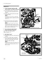
Cassette reference plate
Flange surface
S/T reel table Go end side Not-go end side
Reel table height adjustment tool
The go end side of the gauge slides over the flange
of the reel table.
The not-go end side of the gauge blocks with the
flange of the reel table.
.
Difference between go end side and not-go end side in dimension
is 0.2 mm
Adjutment
screw
Cassette post
S reel table
T reel table
Reel table height
adjustment tool
Cassette post
Cassette reference plate
Reel shafts
(cleaning)
.
T reel tables
Bottom
(cleaning with dry cloth)
Surface
(cleaning)
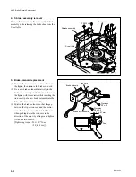
4. Reel shaft cleaning
Clean the reel shaft with cleaning cloth moistened
with cleaning fluid.
5. Reel table cleaning
(1) Clean the surface of the reel table, that the
tension regulator band or S main brake touch,
with cleaning cloth moistened with cleaning
fluid.
(2) Wipe the bottom of the T reel table with dry
cloth.
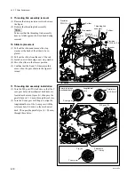
6. Reel table installation (1)
Install the reel table to the reel shaft while
releasing the tension regulator band assembly and
T soft brake arm or S main brake with finger.
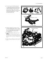
7. Reel table height adjustment
(1) Place the cassette reference plate on the two
cassette posts, then install it as shown in the
figure.
Turn the adjustment screw of the cassette
reference plate and adjust so that no play
exists between the cassette reference plate
and posts.
(2) Move the reel table height adjustment tool to
the flange surface of the S and T reel tables at
intervals of 120 degrees shown in the figure,
and check that the specifications are satisfied.
If the specifications are not satisfied, adjust
according to step (3).
(3) Increase or decrease the number of polywash-
ers under the reel table for adjustment.
When the reel table height is lower than the
specifications;
Insert the polywashers at the top of the reel
table into the bottom of the reel table.
When the reel table height is higher than the
specifications;
Insert the polywashers at the bottom of the
reel table into the top of the reel table.
Reconfirm the specifications.
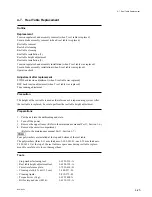
4-7. Reel Table Replacement
Summary of Contents for BVW-55
Page 4: ......
Page 8: ......
Page 50: ...1 40 BVW 55 1 2 3 4 5 6 7 8 9 d l s d l 1 15 Fixtures and Adjustment Equipment List ...
Page 58: ......
Page 106: ......
Page 116: ......
Page 130: ......
Page 148: ......
Page 154: ......
Page 158: ......
Page 169: ...1 9 BVW 55 P2 1 2 Fixtures and Adjustment Equipment List 1 2 3 4 5 6 7 8 9 d l s d l ...
Page 176: ......
Page 272: ......
Page 384: ......
Page 392: ......
Page 396: ...1 2 BVW 55 ...
Page 666: ......
Page 705: ......
Page 752: ......
Page 780: ......
Page 805: ......
Page 848: ......
Page 856: ......
Page 870: ......
Page 884: ......
Page 904: ......
Page 909: ...5 27 b BVW 55 5 27 b CN101 CN301 CN302 CN303 CN901 MB 838 B SIDE SUFFIX 12 MB 838 MB 838 ...
Page 911: ...5 27 a BVW 55 5 27 a CN101 CN301 CN302 CN303 CN901 MB 838 B SIDE SUFFIX 11 MB 838 MB 838 ...
Page 940: ......


