4-47
BVW-55 P2
A
Cam gear
assembly
Logitudinal hole
Logitudinal hole
Hole
Band aligning
plate assembly
Eject link assembly
Lever
Outer slot
Release arm assembly
Shaft b
Shaft c
Shaft a
Shaft
Stop washer
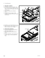
9. Release arm assembly installation
Align the hole and shafts a, b, and c with the pin,
outer slot of cam gear, longitudinal hole of the
eject link assembly, and the longitudinal hole of
the band aligning plate. And then, secure the
release arm assembly with a stop washer.
n
Pull the lever in the direction of the arrow A to
align and insert the shaft b into the longitudinal
hole of the eject link assembly.
10. Tension regulator band installation
Secure the tension regulator band using a new
stop washer.
(Refer to Section 3-9-3.)
11. T tension regulator arm assembly
installation
Secure the T tension regulator arm assembly
using a new stop washer.
(Refer to Section 3-9-4.)
12. Parallel pin removal
Pull the parallel pin out from the S cam gear.
Adjustment after replacement
13. Tape running check
(Refer to Section 5-4.)
14. REV back tension check
(Refer to Section 5-3-2.)
4-13. Cam Gear Assembly Replacement
Summary of Contents for BVW-55
Page 4: ......
Page 8: ......
Page 50: ...1 40 BVW 55 1 2 3 4 5 6 7 8 9 d l s d l 1 15 Fixtures and Adjustment Equipment List ...
Page 58: ......
Page 106: ......
Page 116: ......
Page 130: ......
Page 148: ......
Page 154: ......
Page 158: ......
Page 169: ...1 9 BVW 55 P2 1 2 Fixtures and Adjustment Equipment List 1 2 3 4 5 6 7 8 9 d l s d l ...
Page 176: ......
Page 272: ......
Page 384: ......
Page 392: ......
Page 396: ...1 2 BVW 55 ...
Page 666: ......
Page 705: ......
Page 752: ......
Page 780: ......
Page 805: ......
Page 848: ......
Page 856: ......
Page 870: ......
Page 884: ......
Page 904: ......
Page 909: ...5 27 b BVW 55 5 27 b CN101 CN301 CN302 CN303 CN901 MB 838 B SIDE SUFFIX 12 MB 838 MB 838 ...
Page 911: ...5 27 a BVW 55 5 27 a CN101 CN301 CN302 CN303 CN901 MB 838 B SIDE SUFFIX 11 MB 838 MB 838 ...
Page 940: ......


