4-51
BVW-55 P2
B3
x
14
B3
x
14
CN3
CP-317 board
Fan motor
Fan bracket
Ventilation hole
<At rear side of connector pamel>
Boss
Boss
Boss
Boss
Connector
panel
Attach a motor in this place.
Character
printed side
Replacement
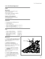
1. Fan motor removal
(1) Remove the two screws, then remove the fan
bracket.
(2) Disconnect the harness connector of the fan
motor connected to CN3 on the CP-317
board, then remove the fan motor.
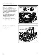
2. Fan motor installation
(1) Wipe off dust on the ventilation hole with a
soft cloth or equivalent.
(2) Place a new fan motor on the rear panel
positioing as shown in the figure. Ensure that
the outer surfaces of the fan motor contact
with four bosses on the panel as shown.
(3) Fit the motor bracket to the fan motor as
shown in the figure, and tighten them with
two screws.
(4) Connect the harness connector of the fan
motor to CN3 on the CP-317 board.
3. Connector panel installation
Install the connector panel to the unit.
(Refer to the maintenance manual Part 1, Section
1-6.)
4. Operation check
(1) Turn on the power.
(2) Check that the fan motor rotates, and blows
off the air from the ventilation hole of the
unit.
4-15. Fan Motor Replacement
Summary of Contents for BVW-55
Page 4: ......
Page 8: ......
Page 50: ...1 40 BVW 55 1 2 3 4 5 6 7 8 9 d l s d l 1 15 Fixtures and Adjustment Equipment List ...
Page 58: ......
Page 106: ......
Page 116: ......
Page 130: ......
Page 148: ......
Page 154: ......
Page 158: ......
Page 169: ...1 9 BVW 55 P2 1 2 Fixtures and Adjustment Equipment List 1 2 3 4 5 6 7 8 9 d l s d l ...
Page 176: ......
Page 272: ......
Page 384: ......
Page 392: ......
Page 396: ...1 2 BVW 55 ...
Page 666: ......
Page 705: ......
Page 752: ......
Page 780: ......
Page 805: ......
Page 848: ......
Page 856: ......
Page 870: ......
Page 884: ......
Page 904: ......
Page 909: ...5 27 b BVW 55 5 27 b CN101 CN301 CN302 CN303 CN901 MB 838 B SIDE SUFFIX 12 MB 838 MB 838 ...
Page 911: ...5 27 a BVW 55 5 27 a CN101 CN301 CN302 CN303 CN901 MB 838 B SIDE SUFFIX 11 MB 838 MB 838 ...
Page 940: ......


