4-54
BVW-55 P2
B2
x
4
B2
x
4
CN6
CN7
CN-1541 board
DP-300 board
4-17. LCD Monitor and Backlight Replacement
4-17-1. Backlight Replacement
Outline
Replacement
DP-300 board removal
Backlights removal
Backlights installation
DP-300 board installation
Precaution
The two backlights are located on the top and bottom at the back side of the LCD
monitor. If either top or bottom of the backlight is turned off because of it reaches at
the end of its useful life, it is recommended to replace both backlights at the same
time.
Preparations
1.
Turn off the power.
2.
Remove the display panel cover. (Refer to Section 3-1-6.)
Tools
.
Torque screwdriver (3 kg
.
cm):
J-6325-400-A
.
Torque screwdriver bit (for M1.4):
J-6325-110-A
.
Torque screwdriver bit (for M2):
J-6325-380-A
Replacement
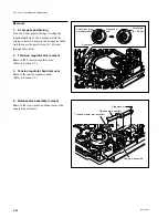
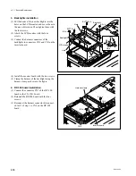
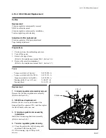
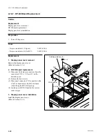
1. DP-300 board removal
(1) Disconnect the harness connector connected
to CN6 on the DP-300 board.
(2) Remove the four screws shown in the figure.
(3) Disconnect the connector CN7 connected to
the CN-1541 board below the DP-300 board
to lift the DP-300 board out.
4-17. LCD Monitor and Backlight Replacement
4-17-1. Backlight Replacement
Summary of Contents for BVW-55
Page 4: ......
Page 8: ......
Page 50: ...1 40 BVW 55 1 2 3 4 5 6 7 8 9 d l s d l 1 15 Fixtures and Adjustment Equipment List ...
Page 58: ......
Page 106: ......
Page 116: ......
Page 130: ......
Page 148: ......
Page 154: ......
Page 158: ......
Page 169: ...1 9 BVW 55 P2 1 2 Fixtures and Adjustment Equipment List 1 2 3 4 5 6 7 8 9 d l s d l ...
Page 176: ......
Page 272: ......
Page 384: ......
Page 392: ......
Page 396: ...1 2 BVW 55 ...
Page 666: ......
Page 705: ......
Page 752: ......
Page 780: ......
Page 805: ......
Page 848: ......
Page 856: ......
Page 870: ......
Page 884: ......
Page 904: ......
Page 909: ...5 27 b BVW 55 5 27 b CN101 CN301 CN302 CN303 CN901 MB 838 B SIDE SUFFIX 12 MB 838 MB 838 ...
Page 911: ...5 27 a BVW 55 5 27 a CN101 CN301 CN302 CN303 CN901 MB 838 B SIDE SUFFIX 11 MB 838 MB 838 ...
Page 940: ......


