4-56
BVW-55 P2
B2
x
4
B2
x
4
BVTT2
x
5
BVTT2
x
5
LCD monitor
Backlight
Backlight
Hook
Hole
Hole
Hole
Holes
B2
x
4
CN3
CN2
B2
x
4
Inverter board
Harness clamp
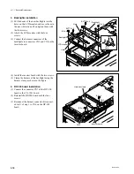
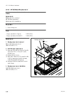
3. Backlights installation
(1) Put the hooks of the new backlights into the
holes on the LCD monitor, and move them in
the arrow directions. Then tighten them with
the four screws.
(2) Attach the LCD monitor with the four
screws.
(3) Connect the harness connectors of the
backlights to connectors CN2 and CN3 on the
inverter board.
4-17-1. Backlight Replacement
(4) Install the inverter board with the two screws.
(5) Clamp the harness of the backlight using the
harness clamp as shown in the figure.
4. DP-300 board installation
(1) Connect the connector CN7 of the DP-300
board to the CN-1541 board.
(2) Reinstall the DP-300 board with the four
screws.
(3) Reconnect the harness connector disconnect-
ed in (1) of step 1 to CN6 on the DP-300
board.
Summary of Contents for BVW-55
Page 4: ......
Page 8: ......
Page 50: ...1 40 BVW 55 1 2 3 4 5 6 7 8 9 d l s d l 1 15 Fixtures and Adjustment Equipment List ...
Page 58: ......
Page 106: ......
Page 116: ......
Page 130: ......
Page 148: ......
Page 154: ......
Page 158: ......
Page 169: ...1 9 BVW 55 P2 1 2 Fixtures and Adjustment Equipment List 1 2 3 4 5 6 7 8 9 d l s d l ...
Page 176: ......
Page 272: ......
Page 384: ......
Page 392: ......
Page 396: ...1 2 BVW 55 ...
Page 666: ......
Page 705: ......
Page 752: ......
Page 780: ......
Page 805: ......
Page 848: ......
Page 856: ......
Page 870: ......
Page 884: ......
Page 904: ......
Page 909: ...5 27 b BVW 55 5 27 b CN101 CN301 CN302 CN303 CN901 MB 838 B SIDE SUFFIX 12 MB 838 MB 838 ...
Page 911: ...5 27 a BVW 55 5 27 a CN101 CN301 CN302 CN303 CN901 MB 838 B SIDE SUFFIX 11 MB 838 MB 838 ...
Page 940: ......


