5-2
BVW-55 P2
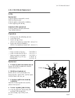
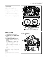
2. Parts location of the tape running system
Following figure describes the names of each component part of the tape running system.
5-1. General Information on Tape Path Adjustment
Impedance roller
(IR-4)
Impedance roller
Drum entrance side (threading end mode)
Drum exit side (threading end mode)
S3 (tension regulator) guide
T6 (tension regulator)
guide
Full-erase head
S4 guide
S2 guide
S1 guide
Tape end sensor
Tape top sensor
Drum assembly
Drum assembly
Lead
Lead
CTL head
Tape cleaner
T2 guide
AT head
T1 guide
T5 guide
T7 guide
T4 guide
Capstan
Pinch roller
T3 guide
Summary of Contents for BVW-55
Page 4: ......
Page 8: ......
Page 50: ...1 40 BVW 55 1 2 3 4 5 6 7 8 9 d l s d l 1 15 Fixtures and Adjustment Equipment List ...
Page 58: ......
Page 106: ......
Page 116: ......
Page 130: ......
Page 148: ......
Page 154: ......
Page 158: ......
Page 169: ...1 9 BVW 55 P2 1 2 Fixtures and Adjustment Equipment List 1 2 3 4 5 6 7 8 9 d l s d l ...
Page 176: ......
Page 272: ......
Page 384: ......
Page 392: ......
Page 396: ...1 2 BVW 55 ...
Page 666: ......
Page 705: ......
Page 752: ......
Page 780: ......
Page 805: ......
Page 848: ......
Page 856: ......
Page 870: ......
Page 884: ......
Page 904: ......
Page 909: ...5 27 b BVW 55 5 27 b CN101 CN301 CN302 CN303 CN901 MB 838 B SIDE SUFFIX 12 MB 838 MB 838 ...
Page 911: ...5 27 a BVW 55 5 27 a CN101 CN301 CN302 CN303 CN901 MB 838 B SIDE SUFFIX 11 MB 838 MB 838 ...
Page 940: ......


