5-20
BVW-55 P2
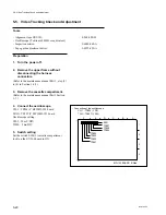
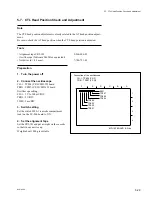
5-5. Video Tracking Check and Adjustment
Tools
.
Alignment tape CR2-1B:
8-960-096-01
.
Oscilloscope (Tektronix 2465B or equivalent)
.
Inspection mirror:
J-6080-840-A
.
Tape guide adjustment driver:
J-6322-420-A
Preparation
1. Turn the power off.
2. Remove the upper frame without
disconnecting the harness
connectors.
(Refer to the maintenance manual Part 1, step (1)
to (4) in Section 1-6-2.)
3. Remove the cassette compartment.
(Refer to the maintenance manual Part1 Section
1-7.)
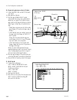
4. Connect the oscilloscope.
CH-1 : TP804 (Y RF)/MD-122 board
TRIG : TP807 (Y SW)/MD-122 board
Oscilloscope setting:
CH-1 : 50 mV/DIV
TIME : 2 ms/DIV
5. Switch setting
Set the switch S100-1 (cassette compartment
lock) on the SV-206 board to ON.
.
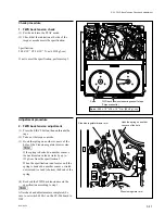
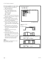
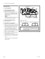
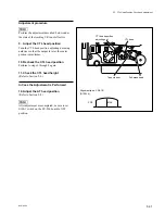
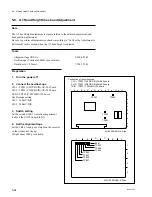
Connection of the oscilloscope
CH-1 : TP804 (Y RF)
TRIG : TP807 (Y SW)
5-5. Video Tracking Check and Adjustment
1
2
3
4
A
B
C
D
E501
TP807
TP806
TP804
TP805
TP803
TP802
TP801
E
F
MD-122 BOARD, B Side
Summary of Contents for BVW-55
Page 4: ......
Page 8: ......
Page 50: ...1 40 BVW 55 1 2 3 4 5 6 7 8 9 d l s d l 1 15 Fixtures and Adjustment Equipment List ...
Page 58: ......
Page 106: ......
Page 116: ......
Page 130: ......
Page 148: ......
Page 154: ......
Page 158: ......
Page 169: ...1 9 BVW 55 P2 1 2 Fixtures and Adjustment Equipment List 1 2 3 4 5 6 7 8 9 d l s d l ...
Page 176: ......
Page 272: ......
Page 384: ......
Page 392: ......
Page 396: ...1 2 BVW 55 ...
Page 666: ......
Page 705: ......
Page 752: ......
Page 780: ......
Page 805: ......
Page 848: ......
Page 856: ......
Page 870: ......
Page 884: ......
Page 904: ......
Page 909: ...5 27 b BVW 55 5 27 b CN101 CN301 CN302 CN303 CN901 MB 838 B SIDE SUFFIX 12 MB 838 MB 838 ...
Page 911: ...5 27 a BVW 55 5 27 a CN101 CN301 CN302 CN303 CN901 MB 838 B SIDE SUFFIX 11 MB 838 MB 838 ...
Page 940: ......


