5-23
BVW-55 P2
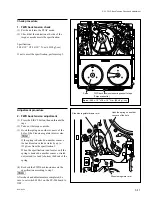
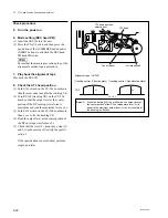
(4) Turn the tracking VR (RV100) so that the
output level of the center portion of RF
envelope waveform is maximized.
(5) Turn the tracking VR (RV100) clockwise so
that the center portion of the RF envelope
waveform makes 80% of its maximum output
level.
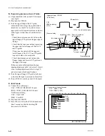
(6) At the state of (5), check that the RF enve-
lope waveform satisfies specification 1.
n
If the level fluctuates, read the average level.
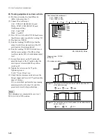
(7) If the level fluctuates, turn the tracking VR
(RV100) on the SV-206 board so that the
output level in the center portion of the RF
envelope waveform is maximized, and check
that the fluctuation amounts satisfy the
specification 2.
If specifications 1 and 2 are not satisfied, perform
the adjustment (at the Drum Entrance Side or the
Drum Exit Side) in steps 19 and later.
12. F. FWD and REV modes
(1) Press the PLAY button to play back the
CR2-1B.
(2) Put the unit into the F. FWD
x
5 mode and
check that the RF waveform satisfies the
specification 3.
(3) Put the unit into the REV
x
5 mode and check
that the RF waveform satisfies the specifica-
tion 3.
If specification 3 is not satisfied in each mode,
perform the adjustment (at the Drum Entrance
Side or the Drum Exit Side) in steps 19 and later.
13. REV
x
x
x
x
x
10 mode to PLAY mode
(1) Press the PLAY button to play back the
CR2-1B.
(2) Put the unit into the REV
x
10 mode once.
Three seconds later, put the unit into the
PLAY mode again.
Check that the RF envelope waveform
returns to the maximum level with the even
level. (Specification 4)
(3) Repeat changing the mode REV
x
10 to
PLAY three times, check that the waveform
satisfies the specification 4 on every time.
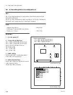
14. Adjust the drum PG phase
(Refer to Section 6-2-1.)
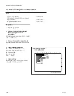
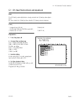
5-5. Video Tracking Check and Adjustment
.
Alignment tape : CR2-1B
(D109 Lit)
.
Alignment tape : CR2-1B
(D109 Dark)
.
Alignment tape : CR2-1B
(D109 Dark)
G
H
J
E
F
I
F
E
>
0.9
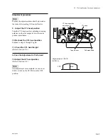
The fluctuation value in each portion of a waveform should be
less than 10 %.
Spec.2:
,
G
H
>
0.9
,
I
J
>
0.9
C
D
A
B
B
A
>
0.8
The output level of the waveform should be more than 80 %
of the maximum value.
Spec.1:
,
C
A
>
0.8
,
D
A
>
0.8
B
A
x
100
>
80 %
Spec. 3:
A
B
A
B
Spec.4
(OK)
(NG)
(NG)
[Drum entrace side]
[Drum exit side]
Returning with even level.
Summary of Contents for BVW-55
Page 4: ......
Page 8: ......
Page 50: ...1 40 BVW 55 1 2 3 4 5 6 7 8 9 d l s d l 1 15 Fixtures and Adjustment Equipment List ...
Page 58: ......
Page 106: ......
Page 116: ......
Page 130: ......
Page 148: ......
Page 154: ......
Page 158: ......
Page 169: ...1 9 BVW 55 P2 1 2 Fixtures and Adjustment Equipment List 1 2 3 4 5 6 7 8 9 d l s d l ...
Page 176: ......
Page 272: ......
Page 384: ......
Page 392: ......
Page 396: ...1 2 BVW 55 ...
Page 666: ......
Page 705: ......
Page 752: ......
Page 780: ......
Page 805: ......
Page 848: ......
Page 856: ......
Page 870: ......
Page 884: ......
Page 904: ......
Page 909: ...5 27 b BVW 55 5 27 b CN101 CN301 CN302 CN303 CN901 MB 838 B SIDE SUFFIX 12 MB 838 MB 838 ...
Page 911: ...5 27 a BVW 55 5 27 a CN101 CN301 CN302 CN303 CN901 MB 838 B SIDE SUFFIX 11 MB 838 MB 838 ...
Page 940: ......


