5-29
BVW-55 P2
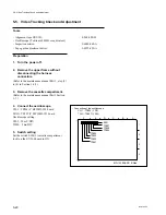
5-7. CTL Head Position Check and Adjustment
Preparation
1. Turn the power off
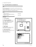
2. Connect the oscilloscope
CH-1 : TP804 (Y RF)/MD-122 board
TRIG : TP807 (Y SW)/MD-122 board
Oscilloscope setting :
CH-1 : 1 V to 200 mV/DIV
TRIG : 5 V/DIV
TIME : 5 ms/DIV
3. Switch setting
Set the switch S100-1 (cassette compartment
lock) on the SV-206 board to ON.
4. Set the alignment tape
Set the CR2-1B and put a weight on the cassette
so that it does not rise up.
Weight about 1000 g is suitable.
5-7. CTL Head Position Check and Adjustment
Note
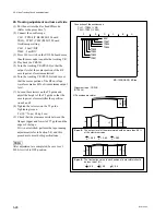
The CTL head position adjustment is closely related to the AT head position adjust-
ment.
Be sure to check the AT head position when the CTL head position is adjusted.
Tools
.
Alignment tape CR2-1B:
8-960-096-01
.
Oscilloscope (Tektronix 2465B or equivalent)
.
Nutdriver (d = 4.5 mm):
7-700-751-01
.
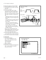
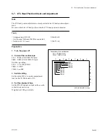
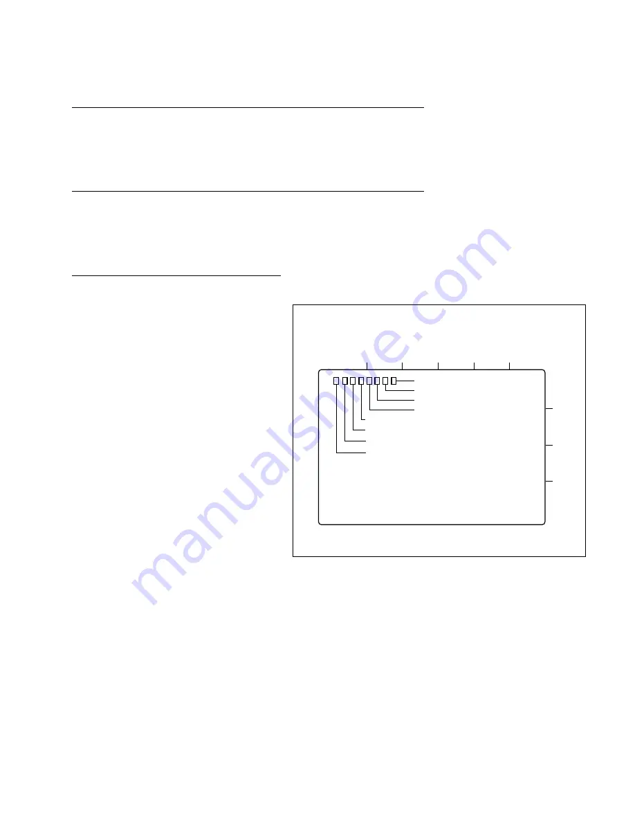
Connection of the oscilloscope
CH-1 : TP804 (Y RF)
TRIG : TP807 (Y SW)
1
2
3
4
A
B
C
D
E501
TP807
TP806
TP804
TP805
TP803
TP802
TP801
E
F
MD-122 BOARD, B Side
Summary of Contents for BVW-55
Page 4: ......
Page 8: ......
Page 50: ...1 40 BVW 55 1 2 3 4 5 6 7 8 9 d l s d l 1 15 Fixtures and Adjustment Equipment List ...
Page 58: ......
Page 106: ......
Page 116: ......
Page 130: ......
Page 148: ......
Page 154: ......
Page 158: ......
Page 169: ...1 9 BVW 55 P2 1 2 Fixtures and Adjustment Equipment List 1 2 3 4 5 6 7 8 9 d l s d l ...
Page 176: ......
Page 272: ......
Page 384: ......
Page 392: ......
Page 396: ...1 2 BVW 55 ...
Page 666: ......
Page 705: ......
Page 752: ......
Page 780: ......
Page 805: ......
Page 848: ......
Page 856: ......
Page 870: ......
Page 884: ......
Page 904: ......
Page 909: ...5 27 b BVW 55 5 27 b CN101 CN301 CN302 CN303 CN901 MB 838 B SIDE SUFFIX 12 MB 838 MB 838 ...
Page 911: ...5 27 a BVW 55 5 27 a CN101 CN301 CN302 CN303 CN901 MB 838 B SIDE SUFFIX 11 MB 838 MB 838 ...
Page 940: ......


