5-31
BVW-55 P2
MAX
Y RF
Adjustment procedure
n
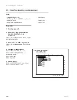
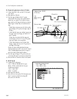
Perform the adjustment described below under
the state of the tracking VR is not effective.
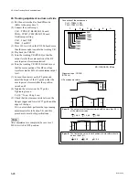
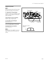
9. Adjust the CTL head position
Turn the CTL head position adjusting nut using
nutdriver so that the output level at the center
portion is maximum.
10. Recheck the CTL head position
Perform to steps 6 through 8 again.
11. Check the CTL head height
(Refer to Section 5-6.)
In Case the Adjustment is Performed
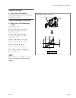
12. Adjust the AT head position
(Refer to Section 5-8.)
n
After adjustment are completed, be sure to set
S100-1 switch on the SV-206 board to OFF
position.
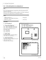
5-7. CTL Head Position Check and Adjustment
.
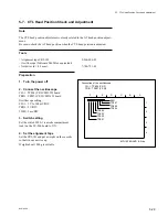
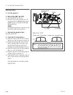
Alignment tape : CR2-1B
(D109 Lit)
CTL head
CTL head position
adjusting nut
Tape cleaner
Full-erase head
Summary of Contents for BVW-55
Page 4: ......
Page 8: ......
Page 50: ...1 40 BVW 55 1 2 3 4 5 6 7 8 9 d l s d l 1 15 Fixtures and Adjustment Equipment List ...
Page 58: ......
Page 106: ......
Page 116: ......
Page 130: ......
Page 148: ......
Page 154: ......
Page 158: ......
Page 169: ...1 9 BVW 55 P2 1 2 Fixtures and Adjustment Equipment List 1 2 3 4 5 6 7 8 9 d l s d l ...
Page 176: ......
Page 272: ......
Page 384: ......
Page 392: ......
Page 396: ...1 2 BVW 55 ...
Page 666: ......
Page 705: ......
Page 752: ......
Page 780: ......
Page 805: ......
Page 848: ......
Page 856: ......
Page 870: ......
Page 884: ......
Page 904: ......
Page 909: ...5 27 b BVW 55 5 27 b CN101 CN301 CN302 CN303 CN901 MB 838 B SIDE SUFFIX 12 MB 838 MB 838 ...
Page 911: ...5 27 a BVW 55 5 27 a CN101 CN301 CN302 CN303 CN901 MB 838 B SIDE SUFFIX 11 MB 838 MB 838 ...
Page 940: ......


