1
BVW-55
Table of Contents
Manual Structure
Purpose of this manual .............................................................................................. 5
Contents ..................................................................................................................... 5
Related manuals ......................................................................................................... 6
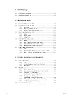
1. Service Overview
1-1.
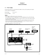
Power Supply .............................................................................................. 1-1
1-2.
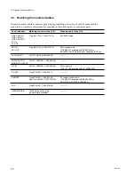
Matching Connectors/Cables ...................................................................... 1-2
1-3.
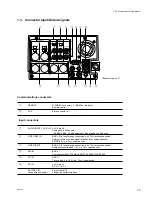
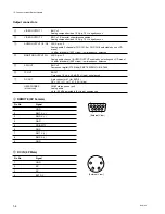
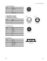
Connector Input/Output signals .................................................................. 1-3
1-4.
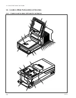
Location of Main Parts and Circuit Functions ............................................ 1-6
1-4-1.
Function and Location of Printed Circuit Boards ...................... 1-6
1-4-2.
Main Mechanical Part Locations ............................................... 1-8
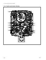
1-4-3.
Function and Location of Sensors ............................................ 1-10
1-5.
System of Cassette .................................................................................... 1-12
1-6.
Removing/Reinstalling the Cabinet .......................................................... 1-13
1-6-1.
Battery Sub Panel ..................................................................... 1-13
1-6-2.
Upper Frame ............................................................................. 1-14
1-6-3.
Connector Panel ....................................................................... 1-16
1-6-4.
Bottom Plate ............................................................................. 1-17
1-7.
Removing/Reinstalling the Cassette Compartment .................................. 1-18
1-8.
Disconnecting/Reconnecting the Printed Circuit Boards .......................... 1-19
1-8-1.
Plug-in Board ........................................................................... 1-19
1-8-2.
DM-121 Board ......................................................................... 1-21
1-9.
Settings for Internal Switches/Slit Lands .................................................. 1-22
1-10. Description on Internal Indicators ............................................................. 1-32
1-11. How to Take Out the Cassette When the Tape is Slacked ........................ 1-36
1-12. Cleaning Clogged Video Heads ................................................................ 1-37
1-13. Power Protection ....................................................................................... 1-37
1-13-1. Overcurrent Protection ............................................................. 1-37
1-13-2. Information on IC Link ............................................................ 1-37
1-14. Battery for Memory Backup ..................................................................... 1-38
1-15. Fixtures and Adjustment Equipment List ................................................. 1-39
1-15-1. Fixtures ..................................................................................... 1-39
1-15-2. Equipment for Adjustment ....................................................... 1-41
1-16. Settings for External Editors ..................................................................... 1-42
1-16-1. Time Code Settings for Recorder ............................................. 1-42
1-16-2. VTR Constant Settings for External Editors ............................ 1-42
1-16-3. System Phase Adjustment ........................................................ 1-43
1-16-4. Setup Menu Setting of ITEM-701 ............................................ 1-43
1-17. Setup Menu ............................................................................................... 1-44
1-17-1. Menu Operation ....................................................................... 1-44
1-17-2. F-Series items ........................................................................... 1-45
1-18. Threading End and Unthreading End States ............................................. 1-46
Summary of Contents for BVW-55
Page 4: ......
Page 8: ......
Page 50: ...1 40 BVW 55 1 2 3 4 5 6 7 8 9 d l s d l 1 15 Fixtures and Adjustment Equipment List ...
Page 58: ......
Page 106: ......
Page 116: ......
Page 130: ......
Page 148: ......
Page 154: ......
Page 158: ......
Page 169: ...1 9 BVW 55 P2 1 2 Fixtures and Adjustment Equipment List 1 2 3 4 5 6 7 8 9 d l s d l ...
Page 176: ......
Page 272: ......
Page 384: ......
Page 392: ......
Page 396: ...1 2 BVW 55 ...
Page 666: ......
Page 705: ......
Page 752: ......
Page 780: ......
Page 805: ......
Page 848: ......
Page 856: ......
Page 870: ......
Page 884: ......
Page 904: ......
Page 909: ...5 27 b BVW 55 5 27 b CN101 CN301 CN302 CN303 CN901 MB 838 B SIDE SUFFIX 12 MB 838 MB 838 ...
Page 911: ...5 27 a BVW 55 5 27 a CN101 CN301 CN302 CN303 CN901 MB 838 B SIDE SUFFIX 11 MB 838 MB 838 ...
Page 940: ......


