3-1
BVW-55
3-1. Overview of Maintenance Mode
This unit has the maintenance mode that is useful during
maintenance and trouble diagnosis.
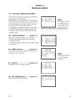
This maintenance mode consists of the four modes below.
The contents of the maintenance mode are superimposed
on the LCD monitor and the video monitor connected to
the VIDEO OUTPUT 2 (SUPER) connector.
To superimpose the contents of the maintenance mode, set
the SUPER item on the general setting page of the sub
LCD menu to ON. (For the sub LCD menu. refer to the
operation manual.)
M0 : TAPE MAINTENANCE ............. (Section 3-2)
This mode is used for maintenance of a VTR part.
In this manual, explains tape maintenance items for
operation check only.
For adjustment and others, refer to the maintenance manual
part 2 volume 1.
M2 : ERROR LOGGER ..................... (Section 3-3)
This mode is used to display the record of errors (error
logging) that occur in this unit.
M3 : OTHERS ................................... (Section 3-4)
This mode is used for checking the others.
M4 : SETUP MAINTENANCE ........... (Section 3-5)
This mode is used for the setup menu.
Section 3
Maintenance Mode
MAINTENANCE MODE
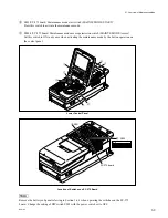
M0 : TAPE MAINTENANCE
M2 : ERROR LOGGER
M3 : OTHERS
M4 : SETUP MAINTENANCE
*
(Mode screen during activation of maintenance mode)
n
The typeface of charac-
ters displayed on the
video monitor differs
from the actual one.
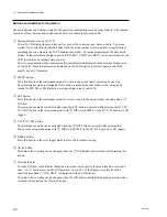
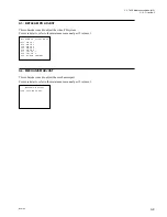
TAPE MAINTENANCE MODE
C0 : SERVO CHECK
C2 : AUDIO/VIDEO CHECK
A0 : SERVO ADJUST
A1 : BETACAM REC ADJUST
A2 : AUDIO/VIDEO ADJUST
A3 : BETACAM PB ADJUST
A4 : MECHANISM ADJUST
*
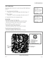
ERROR LOGGER
(001/003)
001 REEL TROUBLE-1
002 TAPE TENSION ERROR
003 INTERNAL I/F ERROR
------------------------
TAPE ERROR ON
WARNING ON
CONDITION ON
'97 09 03 09:23:00
*
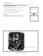
M3:OTHERS
M30:ROM VERSION
M31:SERIAL NUMBER
M35:MEMORY CHECK
M36:HOUR METER RESET
M3F:MEMORY CARD UTILITY
*
SETUP MAINTENANCE MODE
M40 : EXTENDED MENU
M49 : RESET ALL SETUP
*
n
The display on the left is
one of the displayed
examples.
Summary of Contents for BVW-55
Page 4: ......
Page 8: ......
Page 50: ...1 40 BVW 55 1 2 3 4 5 6 7 8 9 d l s d l 1 15 Fixtures and Adjustment Equipment List ...
Page 58: ......
Page 106: ......
Page 116: ......
Page 130: ......
Page 148: ......
Page 154: ......
Page 158: ......
Page 169: ...1 9 BVW 55 P2 1 2 Fixtures and Adjustment Equipment List 1 2 3 4 5 6 7 8 9 d l s d l ...
Page 176: ......
Page 272: ......
Page 384: ......
Page 392: ......
Page 396: ...1 2 BVW 55 ...
Page 666: ......
Page 705: ......
Page 752: ......
Page 780: ......
Page 805: ......
Page 848: ......
Page 856: ......
Page 870: ......
Page 884: ......
Page 904: ......
Page 909: ...5 27 b BVW 55 5 27 b CN101 CN301 CN302 CN303 CN901 MB 838 B SIDE SUFFIX 12 MB 838 MB 838 ...
Page 911: ...5 27 a BVW 55 5 27 a CN101 CN301 CN302 CN303 CN901 MB 838 B SIDE SUFFIX 11 MB 838 MB 838 ...
Page 940: ......


