3-17
BVW-55
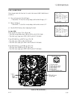
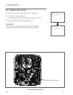
Locations of Threading End and Unthreading End Sensors
3-2. TAPE Maintenance Mode (M0)
3-2-2. SERVO CHECK Mode (C0)
Code transition of the function cam
State of sensors (on the SV-206 board)
Condition of this unit
PH304
PH303
PH302
PH301
(TP304)
(TP303)
(TP302)
(TP301)
1
1
1
0
UNTHREAD END
1
1
0
0
1
1
0
1
THEADING
1
0
0
1
1
0
0
0
1
0
1
0
1
0
1
1
0
0
1
1
0
0
1
0
0
0
0
0
0
0
0
1
0
1
0
1
UNTHREADING
0
1
0
0
0
1
1
0
THREAD END
TP301TP302
TP304
TP303
A
B
C
1
2
3
4
5
6
7
8
SV-206 Board
(A Side)
PH303
PH302
PH304
PH301
Function cam
sensors
Threading link
Function cam
Summary of Contents for BVW-55
Page 4: ......
Page 8: ......
Page 50: ...1 40 BVW 55 1 2 3 4 5 6 7 8 9 d l s d l 1 15 Fixtures and Adjustment Equipment List ...
Page 58: ......
Page 106: ......
Page 116: ......
Page 130: ......
Page 148: ......
Page 154: ......
Page 158: ......
Page 169: ...1 9 BVW 55 P2 1 2 Fixtures and Adjustment Equipment List 1 2 3 4 5 6 7 8 9 d l s d l ...
Page 176: ......
Page 272: ......
Page 384: ......
Page 392: ......
Page 396: ...1 2 BVW 55 ...
Page 666: ......
Page 705: ......
Page 752: ......
Page 780: ......
Page 805: ......
Page 848: ......
Page 856: ......
Page 870: ......
Page 884: ......
Page 904: ......
Page 909: ...5 27 b BVW 55 5 27 b CN101 CN301 CN302 CN303 CN901 MB 838 B SIDE SUFFIX 12 MB 838 MB 838 ...
Page 911: ...5 27 a BVW 55 5 27 a CN101 CN301 CN302 CN303 CN901 MB 838 B SIDE SUFFIX 11 MB 838 MB 838 ...
Page 940: ......

