3-23
BVW-55
C22 : MULTI LOOP (10TIMES)
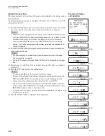
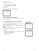
This menu selects the multi-loop function enabled or
disabled in the maintenance mode, and additionally selects
a video test signal when the multi-loop function is enabled.
The video test signal that can be selected is output from an
internal video test signal generator. The video test signal is
the same in type as one described in a C21 : VIDEO TEST
SG menu.
OFF:
Normal state (in which no multi-loop
operation is performed)
Except OFF: The selected signal is output from a video
test signal generator for multi-loop opera-
tion.
Multi-loop function setting
To set the multi-loop function, turn the JOG dial while
pressing the search button and display the desired setting.
This setting is valid until the maintenance mode is termi-
nated. However, the C22 : MULTI LOOP (10TIMES)
setting is reset to OFF when the C21 : VIDEO TEST SG
setting is changed.
m
.
This menu is set to OFF when the maintenance mode is
activated.
.
The output signal during multi-loop operation can also
be recorded on the tape. In this case, press the SET
button and perform the recording operation with the
white square is displayed in the upper-right position of
the LCD monitor.
3-2. TAPE Maintenance Mode (M0)
3-2-3. AUDIO/VIDEO CHECK Mode (C2)
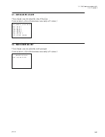
AUDIO/VIDEO CHECK MODE
C22:MULTI LOOP(10TIMES)
OFF
*
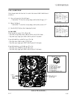
AUDIO/VIDEO CHECK MODE
C23:AUDIO TEST SG
OFF
*
C23 : AUDIO TEST SG
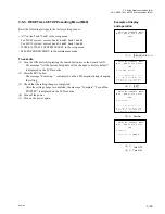
This menu selects the operation in the maintenance mode
of an audio test signal generator incorporated in this unit.
OFF:
The audio test signal generator opera-
tion stops.
1KHz SINE 0VU: The audio test signal generator outputs
the signal (1 kHz sine, 0 VU).
Setting of audio test signal generator
To set the audio test signal generator, turn the JOG dial
while pressing the seach button and display the desired
setting.
This setting is valid until the maintenance mode is termi-
nated.
m
.
This menu is set to OFF when the maintenance mode is
activated.
.
The output signal of a test signal generator can also be
recorded on the tape. In this case, press the SET button
and perform the recording operation with the white
square is displayed in the upper-right position of the
LCD monitor.
Summary of Contents for BVW-55
Page 4: ......
Page 8: ......
Page 50: ...1 40 BVW 55 1 2 3 4 5 6 7 8 9 d l s d l 1 15 Fixtures and Adjustment Equipment List ...
Page 58: ......
Page 106: ......
Page 116: ......
Page 130: ......
Page 148: ......
Page 154: ......
Page 158: ......
Page 169: ...1 9 BVW 55 P2 1 2 Fixtures and Adjustment Equipment List 1 2 3 4 5 6 7 8 9 d l s d l ...
Page 176: ......
Page 272: ......
Page 384: ......
Page 392: ......
Page 396: ...1 2 BVW 55 ...
Page 666: ......
Page 705: ......
Page 752: ......
Page 780: ......
Page 805: ......
Page 848: ......
Page 856: ......
Page 870: ......
Page 884: ......
Page 904: ......
Page 909: ...5 27 b BVW 55 5 27 b CN101 CN301 CN302 CN303 CN901 MB 838 B SIDE SUFFIX 12 MB 838 MB 838 ...
Page 911: ...5 27 a BVW 55 5 27 a CN101 CN301 CN302 CN303 CN901 MB 838 B SIDE SUFFIX 11 MB 838 MB 838 ...
Page 940: ......

