3-27
BVW-55
Setting mode
Display mode
ERROR LOGGER
(001/003)
001 REEL TROUBLE-1
002 TAPE TENSION ERROR
003 INTERNAL I/F ERROR
------------------------
TAPE ERROR ON
WARNING ON
'99 07 03 09:23:17
ERROR LOGGER
(001/003)
001 REEL TROUBLE-1
002 TAPE TENSION ERROR
003 INTERNAL I/F ERROR
'99 07 03 09:23:15
*
*
0
[STOP]
+
[SET]
[Search]
+
DIAL(
2
)
[Search]
+
DIAL(
2
)
ERROR LOGGER
(001/003)
001 REEL TROUBLE-1
002 TAPE TENSION ERROR
003 INTERNAL I/F ERROR
------------------------
TAPE ERROR ON
WARNING ON
'99 07 03 09:23:20
*
0
DIAL(
2
)
ERROR LOGGER
(001/003)
001 REEL TROUBLE-1
002 TAPE TENSION ERROR
003 INTERNAL I/F ERROR
------------------------
TAPE ERROR ON
WARNING OFF
'99 07 03 09:23:22
*
0
ERROR LOGGER
(001/003)
001 REEL TROUBLE-1
002 TAPE TENSION ERROR
003 INTERNAL I/F ERROR
------------------------
TAPE ERROR ON
WARNING ON
'99 07 03 09:23:24
*
0
3-3. Error Logger Display Mode (M2)
3-3-3. Setting Mode
3-3-3. Setting Mode
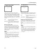
The setting mode is used to display a menu that limits the display of an error log. In
this menu, the display can be turned on and off for each error log category.
A calendar/clock can also be set in this menu.
m
.
The top and second screens on the right are the examples displayed when the error
logger mode and setting mode are first activated after the power is turned on. The
second-time or later screen is displayed with the preceding display completed.
.
A white square mark is displayed in the upper-right position of the LCD monitor
as in the display mode when the SET button is pressed in the setting mode (except
when “Push SET Button” is displayed during calendar/clock setting). The unit
then enters the normal operation state (in which the normal operation of this unit
except a menu system can be performed). The former state is returned when the
MENU button is pressed.
Entering the setting mode
Press the SET button while pressing the STOP button in the display mode.
Returning to the display mode
Press the SET button again while pressing the STOP button or press the MENU
button.
Setting menu
The seventh to tenth lines on the LCD monitor are a setting menu. The display in
the display mode is left in the first to fifth lines.
Each setting when the power is turned on is all ON.
The error log belonging to a category is limited in display when each item is set to
OFF. (Refer to the “Limited-display screen” on the previous page.)
The changed setting is valid until the power is turned off. How to change the setting
is described below.
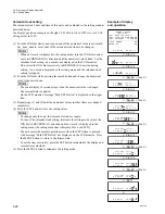
(1) Turn the JOG dial and move the
*
mark to the category to be changed in setting.
m
.
In a sub LCD, the contents of the
*
-marked line are displayed on the LCD
monitor.
.
Turn the JOG dial continuously in FORWARD (
2
) direction for the calen-
dar/clock setting. (Refer to the next page.)
(2) To change the setting from ON to OFF, turn the JOG dial in REVERSE (
3
)
direction while pressing the search button.
To change it from OFF to ON, turn the JOG dial in FORWARD (
2
) direction
while pressing the search button.
(3) To change the setting of other categories, repeat steps (1) and (2).
(4) Press the MENU button to terminate the setting mode.
Example of display
and operation
Summary of Contents for BVW-55
Page 4: ......
Page 8: ......
Page 50: ...1 40 BVW 55 1 2 3 4 5 6 7 8 9 d l s d l 1 15 Fixtures and Adjustment Equipment List ...
Page 58: ......
Page 106: ......
Page 116: ......
Page 130: ......
Page 148: ......
Page 154: ......
Page 158: ......
Page 169: ...1 9 BVW 55 P2 1 2 Fixtures and Adjustment Equipment List 1 2 3 4 5 6 7 8 9 d l s d l ...
Page 176: ......
Page 272: ......
Page 384: ......
Page 392: ......
Page 396: ...1 2 BVW 55 ...
Page 666: ......
Page 705: ......
Page 752: ......
Page 780: ......
Page 805: ......
Page 848: ......
Page 856: ......
Page 870: ......
Page 884: ......
Page 904: ......
Page 909: ...5 27 b BVW 55 5 27 b CN101 CN301 CN302 CN303 CN901 MB 838 B SIDE SUFFIX 12 MB 838 MB 838 ...
Page 911: ...5 27 a BVW 55 5 27 a CN101 CN301 CN302 CN303 CN901 MB 838 B SIDE SUFFIX 11 MB 838 MB 838 ...
Page 940: ......


