background image

1

Install Manual

English

Introduction

This product is a rack mount kit for the Auto Changer BW-
J601.

Caution

The Auto Changer is heavy, weighing approximately 65 
lbs. (30 kg).
You will need at least two people to safely move the Auto 
Changer. Otherwise you may have a back injury or drop 
the Auto changer and damage to it.
Make sure to turn off the Auto Changer and disconnect all 
cables before the installation.

Required Tools

You will need the following tools, screws, and nuts to 
perform this installation.

Tools

• Phillips screwdriver
• Standard screwdriver
• 10/32 inch wrench

Screws and Nuts

You will also need some screws and nuts (sold separately) 
to install the Auto Changer to the rack.
• Eight screws to place the slide rail brackets to the rack.
• Two screws to place the front of the tray to the rack.
• Ten nuts that match the screws above.*

* You will not need the nuts if the rack comes with the nuts 

or the holes of the frames have been tapped. Use the nuts 
if the rack comes with the nuts.

Installation Precautions

Note the following points before the installation.
• The mounting kit fits a rack 900 mm in depth. You 

cannot use any other sized rack.

• The slid rail brackets require between 484 and 488 mm 

in width and 600 and 650 mm in depth to assemble to the 
rack. Ensure that the rack has enough space to place the 
brackets.

• Ensure that the rack frames are assembled with the 

specified value as referred to above.

• Ensure you have adequate ventilation and environmental 

controls to support your Auto Changer.

• Ensure that nothing obstructs the filter at the rear panel 

and the mail slot at the front panel of the Auto Changer.

• The rack must be bolted securely to the floor or equipped 

with a sturdy and extendable anti-tip leg. You must 
prevent the cabinet from tipping forward when one or 
more Auto Changers and other devices are fully 
extended out the front of the rack.

• Ensure that you have adequate power to supply all the 

devices installed in the rack.

• Ensure that you earth the power outlets and power cables 

you are using.

• To avoid producing a static during the installation, keep 

the working environment properly. We recommend 
using an antistatic mat and a wristband.
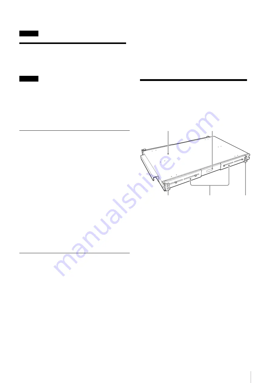
Unpacking

The rack mount kit comes with the following parts:
• Tray (1)
• L-shaped slide rail bracket (4) with screws (8)
• Rail guide (4)
• Rail (2)

• Screws to place the Auto Changer on the tray (6)
• Install Manual (this document) (1)

Slide rail bracket

Rail

Rail guide

Tray

Slide rail bracket

Summary of Contents for BW-A10

Page 1: ...本体をラックに取り付ける前に 以下の 点に注意してください 本ラックマウントキットの取り付け可能なラックの奥行き は 900 mm です それ以外のタイプのラックには取り 付けできません スライドレールブラケットの取り付け寸法は 486 2 mm 幅 650 660 mm 奥行き です 前後左右 のフレームの間隔を確認し スライドレールブラケットが 取り付けできるか確認してください ラックのフレームが規定値どおりか確認してください オートチェンジャー本体の使用環境を確認し その範囲を 保てる場所に設置することをおすすめします オートチェンジャー本体後面のファン 前面のメディア挿 入口付近に ケーブルやその他の障害物がないように設置 してください オートチェンジャー本体をラックに取り付けたときに ラックの重量バランスが崩れて転倒することを防ぐため ラックに転倒防止金具などを取り付けることをお...

Page 2: ... ています スライドレールブラケットを取り付ける スライドレールブラケットを取り付ける位置に フェルトペ ンなどで印を付けておくことをおすすめします ご注意 4 個のスライドレールブラケットの高さを合わせないで本機 を取り付けると 誤動作の原因となりますのでご注意くださ い 1 フレームの 1U の範囲の角穴にナットをはめる メモ ラックにナットがはめ込まれている場合や フレーム にネジタップが付いている場合は この作業は不要で す 以下のようにして 前側と後側のフレームにそれぞれ ナットをはめます 1 前側のフレームにナットをはめる 左右の角穴には外側からナットを 2 個はめ 正面の 角穴には内側からナットを 1 個はめます 2 後側のフレームにナットをはめる 左右の角穴に 外側からナットを 2 個ずつはめます 2 スライドレールブラケットを前側と後側のフレームに 取り付ける 次の図のよ...

Page 3: ...る 一番上と一番下の長穴を使って 止めてください こ こでは 仮止めしておき 後で固定します 3 同様にして 後側のレールガイドを仮止めする 4 左右のレールが平行に取り付けられていること レー ルガイドの外側の間隔が目安として 447 mm になって いることを確認し 手順 2 3 で仮止めしたネジを固定 する 上から見たところ 5 レールの位置を調整し 手順 1 で仮止めしていた六角 ナットを固定する トレイを取り付ける レールガイドのアウターレールに トレイのインナーレール を合わせ ゆっくりスライドさせながら 奥まではめ込む 数回レールを出し入れし トレイが奥まではめ込まれている ことを確認してください ご注意 トレイがしっかりと奥まではめ込まれていないと オート チェンジャーを設置したときに 落下する恐れがあります ラック の正面 前側 ブラケットを最も前寄りに取り 付くように長...

Page 4: ...い 取り付けしやすくなります オート チェンジャーを多少前に出して取り付けすることもで きます 3 付属のネジを使って 底面からオートチェンジャーを 固定する 図のように 6 箇所を固定してください ご注意 作業するときは トレイの脇 正面または背面 から 行ってください トレイの下に入って作業すると 頭 をぶつけたり 万一トレイが落下したときにけがをす る恐れがあります 4 トレイを奥まで入れ お客様で用意したネジを使って フレームに固定する オートチェンジャー本体をラックから 取りはずす ご注意 オートチェンジャー本体の質量は約 30 kg あります 必ず 2 人以上で作業してください 腰を痛めたり 落下し てけがの原因または機器の損傷につながる可能性がありま す 1 オートチェンジャー本体の電源を切る 2 ケーブル類をすべて取りはずす 3 取り付けたときと逆の手順で取りはずす トレイ...

Page 5: ...use any other sized rack The slid rail brackets require between 484 and 488 mm in width and 600 and 650 mm in depth to assemble to the rack Ensure that the rack has enough space to place the brackets Ensure that the rack frames are assembled with the specified value as referred to above Ensure you have adequate ventilation and environmental controls to support your Auto Changer Ensure that nothing...

Page 6: ...se steps if the rack comes with the nuts or the holes of the frames have been tapped Feed and fasten nuts to the front and the rear of the racks as shown in the following figure 1 To the left and right side square holes of the front frame feed the two nuts each from the out side track of the frames then fasten To the front side square holes feed the one nut each from the inside track of the frames...

Page 7: ...e that you assembled the left and right rail guides parallel to each other and the distance between each outer side of the guides keep a guideline measurement as 447mm Then you fasten eight of the provided screws you temporary fastened in the step 2 and 3 View from top 5 Adjust the position of the rails and fasten eight of the provided hexagonal nuts you temporary fastened in the step 1 Slide the ...

Page 8: ... bottom of the tray as shown in the figure below Caution Do not perform these mounting steps from beneath the tray there is a danger of banging your head or sustaining an injury if the tray falls on you Perform these steps from the front or the rear of the tray 4 Slide the tray back until the front flanges on the tray stop the tray Using two of the screws you provided to fasten the front of the tr...

Reviews: