background image

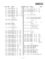
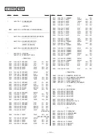
— 36 —

REF.No.

Part No.

Description

Remark

REF.No.

Part No.

Description

Remark

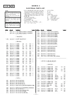
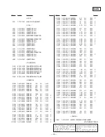
< VIBRATOR >

X301

1-579-833-21 VIBRATOR, CRYSTAL (33MHz)

X401

1-579-175-11 VIBRATOR, CERAMIC (10MHz)

**************************************************************

*

1-659-737-11 SENSOR BOARD

************

< CONNECTOR >

CN851 1-573-383-11 PIN, CONNECTOR (PC BOARD) 2P
CN852 1-750-243-11 SOCKET, CONNECTOR 6P

< DIODE >

D851

8-749-924-18 DIODE PHOTO INTERRUPTER RPI-1391

D852

8-749-924-30 DIODE PHOTO REFLECTOR GP2S28

< RESISTOR >

R851

1-249-416-11 CARBON

820

5%

1/4W

F

R852

1-249-406-11 CARBON

120

5%

1/4W

F

**************************************************************

*

1-647-364-11 TABLE MOTOR BOARD

******************

< MOTOR >

M801

A-4660-525-A MOTOR ASSY, ROTARY (TABLE)

**************************************************************

MISCELLANEOUS
**************

7

1-776-125-11 WIRE (FLAT TYPE) (35 CORE)

9

1-776-124-11 WIRE (FLAT TYPE) (9 CORE)

!

59

1-558-943-61 CORD POWER (E)

!

59

1-575-651-21 CORD POWER (AEP,CH,G,EE)

!

59

1-590-926-11 CORD POWER (US,CND)

!

59

1-696-845-11 CORD POWER (AUS)

!

59

1-751-529-11 CORD POWER (UK)

!

68

1-569-007-11 ADAPTOR, CONVERSION 2P (E)

!

68

1-569-008-11 ADAPTOR, CONVERSION 2P (CH)

72

1-751-052-11 WIRE (FLAT TYPE) (6 CORE)

105

1-466-996-11 ENCODER, ROTARY

109

1-765-443-11 WIRE (FLAT TYPE (23 CORE)

!

751

8-848-367-11 OPTICAL PICK-UP KSS-213B-K/N

!

752

1-769-069-11 WIRE (FLAT TYPE) (16 CORE)

M101

X-4917-523-3 MOTOR ASSY (SPINDLE)

M102

X-4917-504-1 MOTOR ASSY (SLED)

M801

A-4660-525-A MOTOR ASSY, ROTARY (TABLE)

M802

A-4660-914-A MOTOR ASSY, LOADING (LOADING)

!

S601

1-572-675-11 SWITCH, POWER VOLTAGE CHANGE

(VOLTAGE SELECTOR) (E)

S101

1-572-085-11 SWITCH, LEAF (LIMIT)

!

T601

1-423-830-11 TRANSFORMER, POWER (US,CND)

!

T601

1-429-394-11 TRANSFORMER, POWER (EXCEPT US,CND,E)

!

T601

1-429-395-11 TRANSFORMER, POWER (E)

**************************************************************

ACCESSORIES & PACKING MATERIALS

********************************

1-473-519-11 REMOTE COMMANDER (RM-DC41) (C350Z/CE405)
4-941-762-11 COVER (MLY), BATTERY (For RM-DC41)
1-558-271-11 CORD, CONNECTION (AUDIO 108cm)
3-810-585-11 MANUAL, INSTRUCTION

(ENGLISH,FRENCH,SPANISH,SWEDISH, CHINESE)

(CND,AEP,E,CH,UK)

3-810-585-21 MANUAL, INSTRUCTION (ENGLISH) (US,AUS)

3-810-585-31 MANUAL, INSTRUCTION

(GERMAN,DUTCH,PORTUGUESE,ITALIAN) (AEP,G)

3-810-585-41 MANUAL, INSTRUCTION

(SWEDISH,FINISH,DANNISH) (CE405:AEP)

3-810-585-51 MANUAL, INSTRUCTION

(ENGLISH,RUSSIAN,POLISH) (EE)

*

4-979-552-01 CUSHION (F)

*

4-979-553-01 CUSHION (R)

*

4-979-554-01 INDIVIDUAL CARTON (CE405/CE305:AEP)

*

4-979-759-01 INDIVIDUAL CARTON (CE305)

*

4-981-602-01 INDIVIDUAL CARTON (C350Z)

*

4-981-603-01 INDIVIDUAL CARTON (C250Z)

**************************************************************

**************
HARDWARE LIST
**************

#1

7-685-647-79 SCREW +BVTP 3x10 TYPE2 N-S

#2

7-682-548-04 SCREW +BVTT 3x8 (S)

#3

7-685-648-79 SCREW (M3 x 12) TAPPING

#4

7-685-646-79 SCREW +BVTP 3x8 TYPE2 N-S

#5

7-621-772-00 SCREW +B 2x3

#6

7-685-134-19 SCREW +PTPWH 2.6x8 (TYPE2)

#7

7-621-255-15 SCREW +P 2x3

#8

7-685-871-01 SCREW +BVTT 3x6 (S)

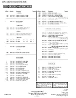
MAIN

SENSOR

TABLE MOTOR

9-960-498-11

English

95L0994-1

Printed in Japan

© 1995. 12

Published by Home A&V Products Div.

Quality Engineering Dept.

Sony Corporation

Consumer A&V Products Company

Home A&V Products Div.

Les composants identifiés par une
marque 

!

 sont critiques pour la

sécurité.
N e   l e s   r e m p l a c e r   q u e   p a r   u n e
piéce portant le numéro spécifié.

T h e   c o m p o n e n t s   i d e n t i f i e d   b y
mark 

!

 or dotted line with mark

!

 are critical for safety.

Replace only with part number
specified.

CDP-C250Z/C350Z/CE305/CE405

Summary of Contents for C350z

Page 1: ...mic range More the 98 dB Harmonic distortion Less than 0 0045 Channel separation More than 100 dB Output Jack Maximum Load type output impedance level LINE OUT Phono 2V Over 10 kilohms jacks at 50 kilohms General Power requirements Where purchased Power requirements US Canadian 120V AC 60 Hz AEP UK German 220 230V AC 50 60 Hz Italian East European Australian 240V AC 50 60 Hz E 110 120V 220 240V ad...

Page 2: ...L PARTS LIST 32 SAFETY RELATED COMPONENT WARNING COMPONENTS IDENTIFIED BY MARK OR DOTTED LINE WITH MARK ON THE SCHEMATIC DIAGRAMS AND IN THE PARTS LIST ARE CRITICAL TO SAFE OPERATION REPLACE THESE COMPONENTS WITH SONY PARTS WHOSE PART NUMBERS APPEAR AS SHOWN IN THIS MANUAL OR IN SUPPLEMENTS PUBLISHED BY SONY ATTENTION AU COMPOSANT AYANT RAPPORT À LA SÉCURITÉ LES COMPOSANTS IDENTIFIÉS PAR UNE MARQU...

Page 3: ...iammeter The Data Precision 245 digital multimeter is suitable for this job 3 Measuring the voltage drop across a resistor by means of a VOM or battery operated AC voltmeter The limit indication is 0 75 V so analog meters must have an accurate low voltage scale The Simpson 250 and Sanwa SH 63Trd are examples of a passive VOM that is suitable Nearly all battery operated digital multimeters that hav...

Page 4: ...ion of arrow to OUT direction To close the disc tray turn the driver in the reverse direction to IN direction Tray 5 Stopper washer 5 NOTE FOR MAIN GAER INSTALLATION 4 Install the MAIN GEAR as show in the drawing 2 Slide the SET LEVER to the arrow B direction B 1 Set the mark of ROTARY ENCODER A 3 Rotate the GEAR U D to the arrow Adirection ...

Page 5: ...buttons 0 manual search buttons play button P pause button p stop button 6 OPEN CLOSE button DISC SKIP button EX CHANGE button ª DISC CHECK button CDP CE305 CE405 only º Remote sensor PEAK SEARCH button CDP CE305 CE405 only EDIT TIME FADE button CDP CE305 CE405 only 10 over 10 button Numeric 1 10 buttons TIME button FADER button MUSIC SCAN button 1 2 3 4 567 8 9 0 ª º AMS is the abbreviation for A...
Page 6: ...3 8 2 Two screws M3 8 8 Flat type wire 35 core MAIN board to CN402 7 Bottom plate 5 Four screws BVTP3 10 2 2 BACK PANEL AND DISC TABLE Three screws BVTP3 10 Disc table B Disc table A Screw BVTP3 8 Bracket guideB1 9 Screw BVTP3 8 0 Bracket guide F1 8 Bracket guide F1 7 Screw BVTP3 8 5 Screw BVTP3 8 6 Bracket guide B1 4 Flat type wire 6 core MAIN board to CN404 1 Connector 2 Five screws BVTP3 10 3 B...

Page 7: ...D board to CN101 3 Two screws PTPWH2 6 6 6 Compression spring BU 7 Compression spring BU 5 Holder BU 1 Stopper washer 5 2 Gear REV 7 Stopper washer 5 8 Gear U D 9 Five screws BVTP3 8 0 Bracket GEAR assembly 3 Stopper washer 5 4 Gear MAIN 5 Screw BVTP3 8 6 Rotary encoder Note As for the installation of the main gear refer to Note for MAIN GAER installation on page 4 ...

Page 8: ...ower switch on 3 Put disc YEDS 18 in to play the number five track 4 Confirm that oscilloscope waveform is clear and check if RF signal level is correct or not BD board TP FE TP VC oscilloscope symmetry A B within 3 1 Vp p BD board TP RF TP VC oscilloscope Note A clear RF signal waveform means that the shape can be clearly distinguished at the center of the waveform RF signal waveform E F Balance ...

Page 9: ...ed Power switch on 3 Put the disc YEDS 18 in to play the number five track Confirm that reading on frequency counter is 4 3218MHz Adjustment Location BD BOARD Conductor Side PLCK RF VC TE FE FEI IC103 1 20 11 10 IC101 MAIN BOARD Conductor Side 40 41 25 24 1 80 65 64 IC401 TP2 ADJ frequency counter BD board TP PLCK ...

Page 10: ... 10 4 1 CIRCUIT BOARDS LOCATION SECTION 4 DIAGRAMS BD BOARD SENSOR BOARD MAIN BOARD DISPLAY BOARD 10 KEY BOARD LOADING BOARD TABLE MOTOR BOARD ...

Page 11: ......

Page 12: ......

Page 13: ......

Page 14: ......

Page 15: ...ut Not used Focus drive output Focus drive output Not used VCO output for analog EFM PLL Not used VCO output for analog EFM PLL GND TEST pin connected normally to GND Digital GND TEST pin connected normally to GND TEST pin connected normally to GND Charge pump output for analog EFM PLL Not used Charge pump output for variable pitch PLL Not used Clock input from variable pitch external VCO GND Anal...

Page 16: ... PSSL 0 Not used DA 11 output when PSSL 1 GTOP output when PSSL 0 Not used DA 10 output when PSSL 1 XUGF output when PSSL 0 Not used DA 09 output when PSSL 1 XPLCK output when PSSL 0 DA 08 output when PSSL 1 GFS output when PSSL 0 DA 07 output when PSSL 1 RFCK output when PSSL 0 DA 06 output when PSSL 1 C2PO output when PSSL 0 Not used DA 05 output when PSSL 1 XRA0F output when PSSL 0 DA 04 output...

Page 17: ...GND Serial data input supplied from CPU Latch input supplied from CPU Serial data transfer clock input supplied from CPU Numbers of track counted signal output Not used Digital power supply Mirror signal output Defect signal output Focus OK output Output to select spindle motor output filter Not used Output to control ON OFF of spindle motor Not used Output to control spindle motor servo Output to...

Page 18: ...laser diode control pin ON H Slit sensor of disc table input pin Latch signal output pin to digital filter IC Serial clock output pin Analog muting control signal output pin Serial data output pin Subcode Q data readout clock output pin Subcode Q data input pin Internal register of SSP DSP readout clock output pin Loading encoder input pin Not used Key input pin A D Not used Disc table feeling and...

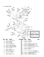
Page 19: ...ce portant le numéro spécifié 2 not supplied 2 not supplied 1 REF No Part No Description Remark 10 X 4946 568 1 PANEL ASSY FRONT CE305 AEP E AUS CH G 10 X 4946 569 1 PANEL ASSY FRONT CE405 US CND 10 X 4946 570 1 PANEL ASSY FRONT CE405 AEP UK E AUS CH G EE 10 X 4946 961 1 PANEL ASSY FRONT C250Z 10 X 4946 962 1 PANEL ASSY FRONT C350Z 11 4 978 492 11 CASE 12 3 703 685 21 SCREW BV 3 x 8 13 3 704 366 0...

Page 20: ...WER US CND 59 1 696 845 11 CORD POWER AUS 59 1 751 529 11 CORD POWER UK 60 4 957 293 01 SPRING RACK RELEASE 61 4 957 291 01 LEVER RACK RELEASE 62 4 957 868 01 SCREW PTPWH 2 6 x 20 63 X 4924 457 1 ROLLER ASSY 64 4 934 376 01 SHAFT ROLLER 65 4 957 292 01 SLIDER RACK 66 4 957 294 01 SPRING D T TENSION 67 4 957 298 01 TABLE A DISC 68 1 569 007 11 ADAPTER CONVERSION 2P E 68 1 569 008 11 ADAPTER CONVERS...

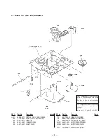
Page 21: ...BU 111 1 452 538 41 MAGNET 112 4 957 281 01 SPRING LOCK LEVER 113 4 957 279 01 LEVER LOCK 114 4 957 303 01 GEAR LOADING C 115 4 934 375 01 GEAR LOADING B 116 4 957 285 01 LEVER SET 117 4 962 087 01 SPRING S TENSION 118 1 659 738 11 LOADING BOARD 119 X 4941 529 1 PULLEY ASSY 120 4 944 490 01 BELT TIMING 121 4 957 555 01 SHEET INSULATING EXCEPT US CND 122 4 957 556 01 SHEET INSULATING EXCEPT US CND ...

Page 22: ... remplacer que par une piéce portant le numéro spécifié REF No Part No Description Remark REF No Part No Description Remark 751 8 848 367 11 OPTICAL PICK UP KSS 213B K N 752 1 769 069 11 WIRE FLAT TYPE 16 CORE 753 4 917 567 21 GEAR M 754 4 951 940 01 INSULATOR BU 755 4 917 565 01 SHAFT SLED 756 4 917 564 01 GEAR P FLATNESS 757 A 4673 509 A BD BOARD COMPLETE 758 4 951 620 01 SCREW 2 6 x 8 BVTP M101...

Page 23: ...CARBON 680 5 1 4W F R720 1 249 417 11 CARBON 1K 5 1 4W F R721 1 249 419 11 CARBON 1 5K 5 1 4W F R722 1 249 421 11 CARBON 2 2K 5 1 4W F R723 1 249 423 11 CARBON 3 3K 5 1 4W F SWITCH S701 1 554 303 21 SWITCH TACTILE 8 S702 1 554 303 21 SWITCH TACTILE 9 S703 1 554 303 21 SWITCH TACTILE 10 S704 1 554 303 21 SWITCH TACTILE 10 S705 1 554 303 21 SWITCH TACTILE EDIT TIME FADE CE305 CE405 S706 1 554 303 21...

Page 24: ...38 1 216 295 91 CONDUCTOR CHIP 2012 R141 1 216 089 91 METAL GLAZE 47K 5 1 10W R142 1 216 081 00 METAL CHIP 22K 5 1 10W R143 1 216 103 91 METAL GLAZE 180K 5 1 10W R144 1 216 103 91 METAL GLAZE 180K 5 1 10W R146 1 216 073 00 METAL CHIP 10K 5 1 10W R147 1 216 081 00 METAL CHIP 22K 5 1 10W R148 1 216 001 00 METAL CHIP 10 5 1 10W R149 1 216 003 11 METAL GLAZE 12 5 1 10W R158 1 216 111 91 METAL GLAZE 39...

Page 25: ...ERAMIC 0 1uF 50V C602 1 126 944 11 ELECT 3300uF 20 16V C603 1 126 942 61 ELECT 1000uF 20 16V C604 1 126 963 11 ELECT 4 7uF 20 50V C605 1 126 963 11 ELECT 4 7uF 20 50V C605 1 126 163 11 ELECT 4 7uF 20 50V C606 1 126 963 11 ELECT 4 7uF 20 50V C607 1 126 941 11 ELECT 470uF 20 6 3V C608 1 104 666 11 ELECT 220uF 20 10V C609 1 124 918 11 ELECT 47uF 20 63V C610 1 124 907 11 ELECT 10uF 20 50V C614 1 104 6...

Page 26: ...1 4W F R310 1 249 417 11 CARBON 1K 5 1 4W F R311 1 249 425 11 CARBON 4 7K 5 1 4W F R312 1 249 437 11 CARBON 47K 5 1 4W R313 1 249 417 11 CARBON 1K 5 1 4W R314 1 249 425 11 CARBON 4 7K 5 1 4W F R315 1 249 425 11 CARBON 4 7K 5 1 4W F R316 1 249 425 11 CARBON 4 7K 5 1 4W F R317 1 249 427 11 CARBON 6 8K 5 1 4W F R318 1 249 427 11 CARBON 6 8K 5 1 4W F R319 1 249 427 11 CARBON 6 8K 5 1 4W F R320 1 249 4...

Page 27: ... US CND T601 1 429 394 11 TRANSFORMER POWER EXCEPT US CND E T601 1 429 395 11 TRANSFORMER POWER E ACCESSORIES PACKING MATERIALS 1 473 519 11 REMOTE COMMANDER RM DC41 C350Z CE405 4 941 762 11 COVER MLY BATTERY For RM DC41 1 558 271 11 CORD CONNECTION AUDIO 108cm 3 810 585 11 MANUAL INSTRUCTION ENGLISH FRENCH SPANISH SWEDISH CHINESE CND AEP E CH UK 3 810 585 21 MANUAL INSTRUCTION ENGLISH US AUS 3 81...

Page 28: ......

Page 29: ......

Page 30: ......

Page 31: ......

Page 32: ......

Page 33: ......

Page 34: ......

Page 35: ......

Page 36: ......

Reviews: