1-5 (E)
CBK-HD02
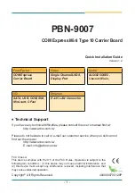
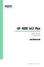
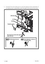
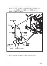
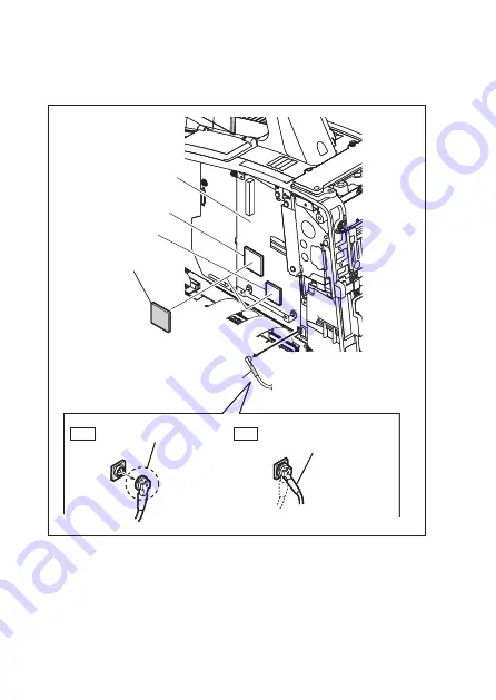
6. Disconnect the coaxial cable (green), remove the protection sheets on both sides of
the radiation sheets, and stick them on IC1505 and IC2902 on the DCP-50 board.
OK
NG
Disconnect the coaxial cable (green)
perpendicularly
Radiation sheets
DCP-50 board
IC1505
IC2902
Hold the plug to remove.
Do not attempt to remove by
pulling the cable.
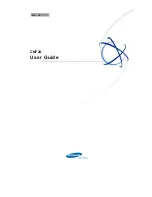
OK
NG
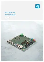
Disconnect the coaxial cable (green)
perpendicularly
Radiation sheets
DCP-50 board
IC1505
IC2902
Hold the plug to remove.
Do not attempt to remove by
pulling the cable.