background image

Usi
ng w

ith

 yo
ur co

mpu

te

r

Using with your computer

77

(and “First Step Guide,” if installed by steps 
11-12) appear on the desktop.

15

Remove the CD-ROM from the disc 
drive of your computer.

If you have any questions about Picture 
Package

Contact information is listed on page 78.

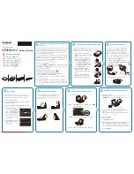
Installing on a Macintosh 
computer

1

Confirm that your camcorder is not 
connected to the computer.

2

Turn on the computer.

Close all applications running on the 
computer before installing the software.

3

Place the CD-ROM in the disc drive of 
your computer.

4

Double-click CD-ROM icon.

5

Copy “FirstStepGuide.pdf,” stored in 
the desired language in the 
[FirstStepGuide] folder, to your 
computer.

6

Then, install ImageMixer VCD2.

7

Copy [IMXINST.SIT] in the [MAC] 
folder of the CD-ROM to a folder of 
your choice.

8

Double-click [IMXINST.SIT] in the 
folder it was copied to.

9

Double-click the unzipped 
[ImageMixerVCD2_Install].

10

When the user acceptance screen is 

displayed, enter your name and 
password.

The installation of ImageMixer VCD2 
starts.

For details on how to use ImageMixer VCD2, 
refer to the software’s on-line help.

Summary of Contents for CCD-TRV138 - Handycam Camcorder - 320 KP

Page 1: ...Model CCD TRV238E AEP Model UK Model East European Model CCD TRV238E TRV438E North European Model CCD TRV138 TRV238E TRV338 TRV438E E Model CCD TRV438E Australian Model Tourist Model Ver 1 0 2004 11 For ADJUSTMENTS SECTION 6 refer to SERVICE MANUAL ADJ 9 876 779 51 INSTRUCTION MANUAL is shown at the end of this document For MECHANISM ADJUSTMENTS refer to the 8mm Video MECHANICAL ADJUSTMENT MANUAL ...

Page 2: ...V138 338 SP 2 h LP 4 h CCD TRV138 338 using 120 min Hi8 Digital8 video cassette CCD TRV138 338 3 0 mm 1 6 type CCD Charge Coupled Device Gross Approx 320 000 pixels Effective Approx 200 000 pixels LCD screen Picture 6 2 cm 2 5 type Total dot number 123 200 560 220 General Power requirements DC 7 2 V battery pack DC 8 4 V AC Adaptor Average power consumption when using the battery pack During camer...

Page 3: ... to apply force on the conductor when soldering or unsoldering Unleaded solder Boards requiring use of unleaded solder are printed with the lead free mark LF indicating the solder contains no lead Caution Some printed circuit boards may not come printed with the lead free mark due to their particular size LEAD FREE MARK Unleaded solder has the following characteristics Unleaded solder melts at a t...

Page 4: ... LENS CONTROL 4 11 VC 341 3 10 LENS DRIVE 4 13 VC 341 4 10 REC PB AMP 4 15 VC 341 5 10 SERVO 4 17 VC 341 6 10 CAMERA MECHA CONTROL 4 19 VC 341 7 10 HI CONTROL 4 21 VC 341 8 10 AUDIO VIDEO 4 23 VC 341 9 10 DC CONTROL 4 25 VC 341 10 10 STEADYSHOT CONNECTOR 4 27 PD 204 LCD DRIVER BACKLIGHT DRIVE 4 29 SI 039 STEADYSHOT JACK 4 31 FP 792 FLEXIBLE 4 31 FP 228 FP 299 FP 300 FP 301 FP 302 FP 802 FLEXIBLE 4...

Page 5: ...hen remove a connector don t pull at wire of connector It is possible that a wire is snapped When installing a connector don t press down at wire of connector It is possible that a wire is snapped 1 2 POWER SUPPLY DURING REPAIRS In this unit about 10 seconds after power is supplied to the battery terminal using the regulated power supply 8 4V the power is shut off so that the unit cannot operate T...

Page 6: ...ompartment 4 Pull the timing belt in the direction of arrow A with a pincette while pressing the cassette compartment take care not to damage to adjust the bending of a tape 5 Let go your hold the cassette compartment and rise the cassette compartment to take out a cassette Pincette Timing belt Timing belt Press the cassette compartment not to rise the cassette compartment DC power supply 5V Adjus...

Page 7: ... The service mode will be displayed and the counter will show the backup No and the 5 character self diagnosis codes 2 Switching of Backup No By rotating the control dial past self diagnosis codes will be shown in order The backup No in the indicates the order in which the problem occurred If the number of problems which occurred is less than 6 only the number of problems which occurred will be sh...

Page 8: ...tape again and perform operations from the beginning Load the tape again and perform operations from the beginning Load the tape again and perform operations from the beginning Load the tape again and perform operations from the beginning Load the tape again and perform operations from the beginning Load the tape again and perform operations from the beginning Load the tape again and perform opera...

Page 9: ... lens block focus reset sensor Pin qs of CN201 of VC 341 board when focusing is performed when the control dial is rotated in the focus manual mode and the focus motor drive circuit IC201 of VC 341 board when the focusing is not performed Inspect the lens block zoom reset sensor Pin qg of CN201 of VC 341 board when zooming is performed when the zoom switch is operated and the zoom motor drive circ...

Page 10: ... qf PD 204 CN6001 qg PD 204 LCD901 ND901 qh Tapping M1 7 x4 qj Hinge assy 6 Lock ace x3 7 Claw 8 Front panel 9 FP 795 CN755 CN009 1 Lift up the EVF 2 Tapping P2 x4 3 Down the EVF 4 EVF block 5 EVF Cabi upper 6 EVF Cabi lower 7 FP 797 LCD902 8 EVF lens 1 Tapping P2 x4 2 Claw x2 3 P Cabi C 1 VC 341 CN004 2 VC 341 CN053 3 Lock ace x3 4 EVF Battely panel block 5 VC 341 CN006 6 Tapping P2 x1 7 Lock ace...

Page 11: ...rced power ON mode Or connect the control key block SS 5100 to the CN006 of VC 341 board and set the power switch to the CAMERA or PLAY EDIT mode Operate the Camera functions of the zoom and focus the VTR function using the adjustment remote commander with the HOLD switch set in the OFF position Setting the Forced Camera Power ON mode 1 Select page 0 address 01 and set data 01 2 Select page D addr...

Page 12: ...aptor AC IN AC adaptor I F unit for LANC control J 6082 521 A CPC jig connector J 6082 539 A CPC jig connector L serices Info LITHIUM battery 7 2Vdc LCD panel PD 204 board Back light unit Adjustment remote commander RM 95 Conductor side CN007 1 16 LANC jack AC IN 2 1 3 ...

Page 13: ...D IMAGER VC 341 A D CONVERTER TIMING GENERATOR CAMERA VTR PROCESS LENS CONTROL LENS DRIVE REC PB AMP SERVO CAMERA MECHA CONTROL HI CONTROL AUDIO VIDEO DC CONTROL STEADYSHOT CONNECTOR PD 204 LCD DRIVE BACKLIGHT DRIVE SI 039 STEADYSHOT JACK SI 039 VC 341 CD 465 PD 204 FP 792 FP 795 CF 5100 PR 5100 SB 9000 SS 5100 FP 797 FP 794 ...

Page 14: ...ELP CCD TRV138 TRV238E TRV338 TRV438E HELP Sheet attachment positions and procedures of processing the flexible boards harnesses are shown Note Close the LCD panel when you work Claw Claw Harness PD 124 ...

Page 15: ...2 5 OVERALL BLOCK DIAGRAM 4 5 OVERALL BLOCK DIAGRAM 3 5 POWER BLOCK DIAGRAM 1 2 OVERALL BLOCK DIAGRAM 5 5 OVERALL BLOCK DIAGRAM 1 5 POWER BLOCK DIAGRAM 2 2 OVERALL BLOCK DIAGRAM 2 5 OVERALL BLOCK DIAGRAM 4 5 OVERALL BLOCK DIAGRAM 3 5 POWER BLOCK DIAGRAM 1 2 OVERALL BLOCK DIAGRAM 5 5 OVERALL BLOCK DIAGRAM 1 5 ...

Page 16: ... 15 13 4 5 7 16 A V OUT CONTROL KEY BLOCK CF 5100 1 2 20 18 17 1 4 IC951 IC151 1 7 ı 9 11 ı 14 14 6 ı 8 19 21 ı 23 40 XRST VTR 42 CAM DD ON CK CONT 1 2 2 ı 11 CL IC801 PITCH AD OVERALL 2 5 PAGE 3 4 S H AGC A D CONVERTER 1 10 IC152 22 21 18 IC271 STEADY SHOT 10 10 8 12 2 18 IR_ON INT MIC XF TALLY LED AV JACK IN IR ON RG H1 H2 1 ı 4 25 26 31 28 XNS SW D001 V1 V4 OVERALL 2 5 PAGE 3 3 33 31 58 20 11 T...

Page 17: ...LL 4 5 PAGE 3 8 XRF AGC OFF 6 25 RF AGC CONT 25 IC251 EVR D A CONVERTER 4 10 17 ı 19 AFC F0 ADJ 23 HALL OFFSET HALL GAIN HALL REF 27 28 3 15 REC Y MT CONT 4 REC L CONT 5 MT FO 26 DOC DET 24 RP IR 21 REC BIAS 20 MT Q 3 48 15 12 8 32 19 7 XMP ME 22 FRQ TUNE 12 A FADE 9 1 5M DEV 10 AU BPF 46 7 13 BOTH REC AGC SLOW DOP DOP RP PB MODE IC481 REC PB AMP 4 10 27 28 5 7 11 34 33 Q481 483 38 39 7 9 2 3 14 1...

Page 18: ...1 CAP FWD CAP ON 166 CAP FWD 25 9 24 IC401 1 3 IC401 2 3 FG PG LED DRIVE TAPE LED K ZM RST LED FC RST LED LENS TEMP AD 5 OVERALL 1 5 PAGE 3 1 4 12 A SERVO SIGNAL 49 50 127 93 IRIS PWM XCS AU 62 185 AV JACK IN 110 XNS SW 128 HALL AD 129 PITCH AD 130 YAW AD 1 IC602 EEPROM 6 10 2 5 6 87 86 84 15 14 1 CN007 2 3 CPC FOR CHECK 190 118 64 67 75 77 7 8 3 1 X601 20MHz XCS EEP IC701 SO IC701 SI IC701 SCK XC...

Page 19: ...10 CHARGE CONTROL 4 3 2 6 5 1 DC IN 22 RESET SW CUSTOM LED ON 9 IC701 CN002 2 2 IC051 2 2 EASY D002 XCHARGE LED 6 CHG D004 XCAM LED 11 XCAM LED 8 CAMERA D002 XVTR LED 9 XVTR LED 9 PLAY EDIT D001 49 45 38 26 VTR DD ON XCS DD XRESET VBAT REG 3V D 1 5V BL REG CAM 7 5V EVER 3 0V CAM 15V EP 13 5V PANEL 15 3V VOUT D053 S002 XBATT INFO SW 6 DISP BATT INFO SW S001 BATTERY CHARGE DETECTOR 14 23 ı 26 OVERAL...

Page 20: ...02 ND901 BACKLIGHT BL HIGH BL LOW BL DET 45 42 43 46 ı 48 28 11 19 ı 21 5 ı 10 12 ı 18 BL REG 10 3 CN6001 2 2 XCS LCD DA PANEL R PANEL G PANEL B PANEL R PANEL G PANEL B XCS LCD DA PANEL XVD BL CONT BL CONT OVERALL 2 5 PAGE 3 3 C SYNC XHD D6004 18 10 7 ı 5 8 4 11 ı 13 1 PANEL HOLD PANEL XVD C SYNC XHD PANEL HOLD 14 9 A VIDEO SIGNAL 2 6 14 16 29 32 35 3 9 3 10 3 5 OVERALL BLOCK DIAGRAM 5 5 Number in...

Page 21: ... 2 2 PAGE 3 13 PD 204 BOARD CHARGE CONTROL IC051 DC CONTROL RESET 9 10 55 30 59 22 34 60 23 14 38 15 3V REG 7 5V REG 17 19 18 16 4 2 EP 13 5V VL 16V VC 341 BOARD 1 2 PANEL 4 6V PANEL 15 3V PANEL 13 5V PANEL 2 8V BL CONT BL REG BL HIGH CN6003 ND901 BACK LIGHT 2 5INCH COLOR LCD UNIT LCD901 CN6001 18 19 16 17 4 2 24 1 3 23 10 VSH5V VGL VGH VSH3V IC6001 L6004 L6001 CN6004 Q6004 6005 6008 6009 BACKLIGH...

Page 22: ... 4 8 8 T REEL S REEL SENSOR M2100 M2101 MECHA DECK VTR DD ON CAM DD ON XCS DD BATT IN HI EVER SO VC 341 BOARD 2 2 17 FUNCTION SWITCH D 2 8V D 2 8V D 2 8V D 2 8V CUSTOM LED VDD CN755 STEADY SHOT 10 10 CAPSTAN FG HU HV HW TAPE LED D001 CN004 3 EP 4 6V EVF DD ON B W LCD UNIT LCD902 VIDEO HEAD 7 4 VOUT VOUT BATTERY CHARGE DETECTOR L481 IC602 IC601 IC401 DRUM CAPSTAN LOADING MOTOR DRIVE 5 10 IC251 IC30...

Page 23: ...PANEL_HOLD XVC_SCK PANEL_G PANEL_B AD5 PANEL_2 8V C SYNC XHD BL_GND PANEL_2 8V REG_GND VC_SI HDO AD5 VC_SO PANEL_R XCS_LCD_DA SE_GND PANEL_G PANEL_HOLD PANEL_ 15 3V PANEL_13 5V BL_REG PANEL_XVD BL_CONT PANEL_B XVC_SCK PANEL_4 6V XCS_EEP REG_GND REG_GND XLANC_PWR_ON SWP_DIR REG_GND LANC_IN EEP_SO PB_RF CAP_FG BPF_MONI LANC_OUT EEP_SCK REC_RF EEP_SI PB_RF MS_LED_VDD N C REG_GND XCUSTOM_LED_ON D_2 8V...

Page 24: ...FP 228 FP 299 FP 300 FP 301 FP 302 FP 802 FLEXIBLE BOARD VC 341 BOARD 3 10 LENS DRIVE VC 341 BOARD 10 10 STEADYSHOT CONNECTOR VC 341 BOARD 4 10 REC PB AMP VC 341 BOARD 5 10 SERVO VC 341 BOARD 7 10 HI CONTROL VC 341 BOARD 8 10 AUDIO VIDEO VC 341 BOARD 9 10 DC CONTROL CONTROL KEY BLOCK SS 5100 CONTROL KEY BLOCK PR 5100 CONTROL KEY BLOCK SB 9000 CONTROL KEY BLOCK CF 5100 VC 341 BOARD 1 10 A D CONVERT...

Page 25: ... between the measurement points and ground when camera shoots color bar chart of pattern box They are reference values and reference waveforms VOM of DC 10 MΩ input impedance is used Voltage values change depending upon input impedance of VOM used Kinds of capacitor Case size External dimensions mm Yellow A A B B A B Fig a Video output terminal output waveform H Cyan Green White Magenta Red Blue F...

Page 26: ...3 V1 4 NC 5 GND 6 7 CCD_OUT VDD 8 NC 9 SUB 10 VL 11 RG 12 H1 13 H2 14 100uH L951 2SC4178 F13F14 T1 Q951 14P CN951 1 2 3 4 5 6 7 8 9 10 11 12 13 14 1 A C954 XX 0 1u C955 XX C952 16V 22u C951 10V 47u C953 10 R952 10k R953 CAM_15V V4 GND H1 V2 CCD_OUT H2 V1 V3 GND RG VSHT GND CAM 7 5V BUFFER IC951 CCD IMAGER 1 10 VC 341 CN151 PAGE 4 9 FP 794 FLEXIBLE THROUGH THE B 3 2 E 5 4 6 D C 05 7 CCD IMAGER CD 4...

Page 27: ..._SO AD7 XVC_SCK XV1 C167 1u C151 XX 1SV329 TPL3 D151 C173 470p C163 0 01u 0 1u C171 2 2u C157 C159 XX XX R158 0 1u C169 PBLK AD8 XSG1 AD4 R153 XX V_STOP 0 1u C160 AD1 IC_801_Y_OUT AVD C166 0 01u ID 0uH FB151 CK_CONT1 AD10 C168 1u C153 XX R157 XX AD9 CAM_ 7 5V 1M R162 XX R159 C172 0 22u AD2 REG_GND 1u C161 FRQ_TUNE 0 001u C152 CL XX R156 1u C170 CLP1 C164 8p X151 A_2 8V CXD2444AR T4 IC151 1 CLPDM 2...

Page 28: ...OSD_R_ON 181 OSD_L_ON 182 CLP1 183 DVSS11 184 ADCK 185 DVDD5 186 ADIN9 187 ADIN8 188 ADIN7 189 ADIN6 190 ADIN5 191 ADIN4 192 ADIN3 193 ADIN2 194 ADIN1 195 ADIN0 196 PLLENB 197 CCDCKL 198 IN_VDD3 199 XTALIN 200 XTALOUT 201 IN_VSS3 202 PDVSSC 203 PAVSSC 204 PAVDDC 205 PDVDDC 206 PDVDDB 207 PAVDDB 208 PAVSSB 209 PDVSSB 210 VSSA9 211 TESTDAC 212 DAO9 213 CBU9 214 REXT9 215 VDDAA9 216 XCS_OSD PBLK 10uH...

Page 29: ... 6 2 1 3 5 4 DIR0A FC_RST_LED 220k R207 470k R209 HALL_AD IRIS_COM 10uH L201 HALL_OFFSET LENS_DET HALL_REF HALL_GAIN XNS_SW 47k R216 LENS_TEMP_AD REG_GND RB201 1k 1 2 3 4 5 6 7 8 470k R208 IRIS_PWM EN1 DIR1A 470p C207 DIR0B RB203 47k 1 2 3 4 5 6 7 8 RB202 22k 1 2 3 4 5 6 7 8 Q201 RN1119FV TH3SONY 10uH L202 XX D203 1 A 0 01u C214 0 47u C212 2200p C215 0 1u C205 4 7u C204 C219 XX XX R218 0 01u C202 ...

Page 30: ...H L484 220uH L481 AGC_SLOW RP_PB_MODE REC_RF PB_C_RF 2SA1965 S TL Q481 RB483 2200 1 2 3 4 5 6 7 8 RN2111FV TL3SONY Q485 PB_C_RF FB481 Q482 2SA1832FV TH3SONY 11P CN481 1 2 3 4 5 6 7 8 9 10 11 BOTH_REC RB481 22k 1 2 3 4 5 6 7 8 RN1104FV TL3SONY Q484 4 7u C498 0 01u C496 0 1u C493 4700p C509 0 01u C508 0 47u C513 0 001u C507 0 01u C515 0 01u C514 0 01u C481 6 3V 33u C482 0 01u C488 0 01u C483 0 022u ...

Page 31: ...4 DFC 55 DFILTER 56 UIN 57 VIN 58 WIN 59 COM 60 D_PGND 61 NC 62 NC 63 D_U 64 D_VS 65 D_V 66 NC 67 D_VS 68 D_W 69 L_OUT1 70 L_VM 71 NC 72 L_OUT2 73 L_PGND 74 C_U 75 C_VS 76 C_V 77 C_VS 78 C_W 79 NC 80 CAPON RN1110FV TL3SONY Q401 M 1 A 0 047u C431 1u C429 0 022u C430 470p C442 0 1u C443 1u C441 0 R431 10k R424 15k R426 R414 0 01u C445 4700p C427 C435 2 2u 0 01u C444 R427 R413 0 01u C426 0 1u C423 0 ...

Page 32: ..._VD HI8_MP_SW XCS_IC_401 YAW_AD PITCH_AD DA_STRB CAP_FWD XSYS_RST LCD_HOLD FC_RST_LED IRIS_PWM LENS_TEMP_AD HALL_AD OSD_SO EEP_SO CH_SCK TAPE_END V_LIGHT_PWM V_LIGHT_PWM MECHA_HD CAM_DD_ON BEEP EVF_DD_ON SYS_V XCS_IC_701 IC_701_SI IC_701_SO XSYS_RST REC_CRRT0 EEP_SI EEP_SO EEP_SCK DRUM_PWM AV_JACK_IN PITCH_AD EEP_SI XREEL_HALL_ON TAPE_LED_ON CAP_FWD CAP_FG CAP_ON HI8_MP_SW ME_SW MODE_SW_C MODE_SW_...

Page 33: ...ON HI_EVER_SCK LANC_IN XBATT_INFO_SW XCHARGE_LED SYS_V BATT XEXT XCAM_LED XCS_DD OSD_V XCHARGE_LED SIRCS_PWM VTR_DD_ON XRESET SYS_V KEY_AD0 KEY_AD1 KEY_AD7 IC_701_SCK KEY_AD5 HI_EVER_SCK DIAL_B XMODE_SW IC_701_SCK INIT_CHARGE_ON XCC_DOWN IC_701_SO LANC_OUT BATT_SIG IC_701_SI SIRCS_PWM XPOWER_SW XLANC_PWR_ON XCS_IC_701 SIRCS_SIG BATT_IN FAST_CHARGE BATT_IN XLANC_PWR_ON LANC_OUT KEY_AD3 XEJECT_SW KE...

Page 34: ...5 6 3V 22u C815 16V 10u C817 4 7u C811 47k R811 470k R817 6 3V 22u C801 16V 10u C807 16V 10u C805 6 3V 22u C808 16V 10u C802 1u C810 0 01u C806 0 5 47k R807 2200 R806 4700 R812 10k R810 0 1u C812 0 1u C814 0 01u C816 1u C835 0 01u C832 0 47u C821 0 01u C837 0 1u C829 0 47u C818 50V 3 3u C820 0 01u C842 16V 10u C841 68p C844 0 01u C843 0 001u C840 820 R819 4V 100u C848 22u 6 3V C849 150k R815 XCS_A...

Page 35: ... 7uH L064 MAS3132E0LS0 D054 1 2 3 A_4 6V 2SC4738FV TH3SONY Q066 CAM_ 7 5V D_2 8V 4 7uH L060 6P CN053 1 2 3 4 5 6 22uH L063 2SB798 T1 Q053 DLDK 33uH L057 VL_16V CPH5815 TL E Q059 2 4 3 5 1 UPA1858GR 9JG E2 A Q052 1 4 2 3 8 5 6 7 CAM_DD_ON XRESET DF3A6 8FV D051 TH3SONY 3 2 1 1 2 3 4 A 1k R051 1M R062 6800 R068 100k R053 10 R064 1200 R067 10u C073 C071 4 7u 0 1u C060 33k R070 27k R066 0 R076 22k R078...

Page 36: ...XCS_LCD XCAM_LED XEJECT_SW PANEL_VD PANEL_HD EVF_G BW_Y KEY_AD0 KEY_AD1 KEY_AD2 KEY_AD3 DIAL_A DIAL_B XRESET V_LIGHT_PWM INT_MIC XF_TALLY_LED SIRCS_SIG SIRCS_PWM AV_JACK_IN VIDEO_I O IR_ON EVF_G BW_Y PANEL_VD PANEL_HD EVF_DD_ON KEY_AD0 XBATT_INFO_SW CUSTOM_LED_ON KEY_AD1 KEY_AD3 KEY_AD2 DIAL_A DIAL_B XRESET INT_MIC XF_TALLY_LED SIRCS_SIG IR_ON SIRCS_PWM VIDEO_I O AUDIO_L_I O AV_JACK_IN XCS_EEP SWP...

Page 37: ...010 470 R6014 XX R6011 10V 4 7u C6007 1 10W 1800 R6005 0 015u C6011 0 1u C6009 560p C6010 68k R6009 1 16W 0 5 100k R6013 0 5 10k 1 16W R6012 0 1u C6001 1u C6002 0 01u C6006 22u 4V C6019 3 3u 25V C6020 0 1u C6027 6 3V C6026 22u R6029 XX XX R6035 XX R6036 XX C6030 XX R6042 0 01u C6005 0 01u C6003 0 01u C6004 XX R6002 R6001 XX 6P CN6006 1 2 3 4 5 6 XX R6047 1200 R6043 3900 R6044 12k R6045 27k R6046 X...

Page 38: ...PW500BS TL2 LAND1 1 A 0 R761 XX R759 XX R762 XX R760 XX R751 XX R754 470 R763 56 R753 56 R752 XX R755 4 7u C758 4 7u C759 XX C751 4V XX C755 4V XX C753 XX C752 XX C757 XX C754 J752 2 L 3 V 1 GND 7 R 5 SW 4 BR FB753 VIDEO_I O REG_GND S_C_I O N C LIA2 REG_GND REG_GND MT_5V S_Y_I O N C INT_MIC REG_GND VL MIC_GND VREF1 RFU_DC N C RFU_DC N C DCOUT_JACK_IN N C LIA1 AUDIO_L_I O MIC_GND MT_5V D_2 8V REG_G...

Page 39: ...ced as block so that PRINTED WIRING BOARD is omitted S003 XX 1 2 3 4 RV001 20k S002 S001 D001 D002 XX D003 D004 1 A R001 1k START STOP EJECT T ZOOM STATIC GND LND001 1 2 3 4 5 6 7 8 9 10 11 12 13 14 XEJECT_SW N C REG_GND D_2 8V N C MODE_LED_VDD XS S_SW XCAM_LED N C XPOWER_SW REG_GND XMODE_SW XVTR_LED ZOOM_VR REG_GND XPOWER_SW XMODE_SW POWER MODE_SW 16 15 CHARGE_LED_VDD XCHARGE_LED W S004 POWER MOD...

Page 40: ...A2 2 B1 4 B2 S010 1 A1 3 A2 2 B1 4 B2 S014 1 A1 3 A2 2 B1 4 B2 1 A 8200 R020 1200 R005 27k R022 3900 R017 1500 R009 2200 R013 8200 R023 2200 R016 1200 R007 2200 R015 1200 R006 R014 2200 1200 R008 3900 R018 3900 R019 1500 R010 1500 R011 8200 R021 1500 R012 10k R003 10k R004 10k R002 10k R001 DATE TITLE EXPOSURE FOCUS END SEARCH EASY DUB MENU VOLUME FADER LI_3V KEY_AD0 XRESET KEY_AD3 D_2 8V KEY_AD2 ...

Page 41: ... BOARD SIDE A SI 039 BOARD CD 465 BOARD CIRCUIT BOARDS LOCATION COMMON NOTE FOR PRINTED WIRING BOARDS MOUNTED PARTS LOCATION FLEXIBLE BOARDS LOCATION WAVEFORMS CIRCUIT BOARDS LOCATION COMMON NOTE FOR PRINTED WIRING BOARDS MOUNTED PARTS LOCATION FLEXIBLE BOARDS LOCATION WAVEFORMS Board Name Function CD 465 CCD IMAGER VC 341 A D CONVERTER TIMING GENERATOR CAMERA VTR PROCESS LENS CONTROL LENS DRIVE R...

Page 42: ...l designation THIS NOTE IS COMMON FOR PRINTED WIRING BOARDS 2 1 3 2 1 3 2 1 3 3 4 5 2 1 1 2 3 6 5 4 E B C 3 1 5 2 4 6 1 2 3 6 5 4 3 1 5 2 4 6 1 2 3 5 4 4 3 1 2 3 1 2 4 5 5 3 4 1 2 1 4 2 3 4 6 2 5 3 1 1 2 4 3 1 4 2 3 Chip parts Transistor Diode Board Name Parts Location Pattern Shown on Page Total Number of Layers Layers Not Indicated CD 465 4 layers 2 to 3 layers VC 341 4 59 4 layers 2 to 3 layers...

Page 43: ... R952 R953 CN951 C951 C952 C953 C954 C955 1 14 7 8 1 13 2 B E C 14 1 6 8 7 9 3 2 4 5 05 CD 465 BOARD 1 860 933 12 22 Note IC951 is not included in CD 465 complete board 4 42 CD 465 4 41 CD 465 Note for Printed Wiring Board See page 4 39 Uses unleaded solder ...

Page 44: ...01 C702 C703 C704 C705 C707 C514 C708 C515 C709 CN151 C710 X701 C711 X702 C712 C713 C714 C715 CL602 CL604 CL605 C331 CL606 CL609 CL801 C339 CL802 CL803CL804 CL610 CL805 CL611 CL612 CL613 CL614 CL616 CL617 CL618 Q001 Q002 Q202 RB203 L201 D701 RB601 RB602 RB603 RB605 RB606 RB608 RB610 RB612 RB613 IC701 Q051 Q052 Q053 Q054 R001 R002 R003 R004 L051 R005 L052 R006 R007 L053 L054 L055 L056 L057 L058 L05...

Page 45: ...03 R104 R105 L151 R106 R107 R108 R109 IC051 R301 R302 R303 R110 R111 R306 R307 R114 R308 R309 R116 IC251 R310 R311 R312 R313 R314 R315 R316 R317 R318 R319 R320 R321 R322 R323 R324 R325 R326 R327 R328 R329 IC271 R330 R331 R332 R334 C105 R335 FB151 FB152 C106 R336 C107 C108 R338 C109 R339 C301 C302 C303 C110 R340 C304 C111 C305 R341 C306 C307 C308 R151 C309 R152 R153 C500 R155 R156 C503 R157 R158 C3...

Page 46: ... C6030 R6008 R6009 IC6001 C6032 R6010 R6011 LND605 R6012 R6013 R6014 R6019 R6020 R6026 R6029 R6030 R6031 R6032 R6035 R6036 R6039 R6040 R6041 R6042 T6001 RB6001 RB6002 RB6003 FB6001 FB6002 CN6004 CN6005 R6043 R6044 R6045 R6046 R6047 CN6006 6 1 20 A A 1 12 36 25 48 13 37 24 1 24 1 1 6 CB E 10 1 C B E C B E 1 4 6 1 4 6 1 6 10 3 4 1 2 8 2 1 7 8 2 1 7 3 3 8 2 1 7 5 C B E Q6003 Q6002 6 1 3 4 2 3 5 2 4 5...

Page 47: ...ALLY FP 792 1 860 929 D753 754 IR EMITTER LND751 LND752 SE752 PITCH LND754 LND755 LND756 LND759 LND760 FB751 FB752 VDR757 R751 R762 CN755 C751 C755 C757 A 1 3 2 4 7 1 2 2 4 5 3 2 1 29 30 D753 D754 IC751 J751 J752 J753 1 3 4 6 5 2 1 7 8 3 1 4 3 A V OUT Note D753 D754 IC751 and J752 are not included in SI 039 complete board Note D001 D002 and D003 are not included in FP 792 flexible board MIC901 MIC...

Page 48: ...RD 1 680 434 1 4 MR SENSOR C B A COM 1 677 049 11 12 11 FP 300 FLEXIBLE BOARD COMPONENT SIDE FP 802 FLEXIBLE BOARD CONDUCTOR SIDE FP 302 FLEXIBLE BOARD CONDUCTOR SIDE 1 680 438 1 689 290 1 680 437 1 680 436 D001 TAPE LED Q002 TAPE END SENSOR H001 T REEL SENSOR S002 C C LOCK S001 REC PROOF H002 S REEL SENSOR FP 301 FLEXIBLE BOARD CONDUCTOR SIDE 1 1 1 2 4 3 1 2 4 3 15 15 1 15 Q001 TAPE TOP SENSOR o ...

Page 49: ...C951 3 REC 7 6 Vp p IC951 2 REC 22 Vp p IC951 1 REC 7 6 Vp p 5 IC951 7 REC 1 2 Vp p 6 IC951 qf REC 3 6 Vp p V H V V H IC951 q REC 23 Vp p 7 IC951 qd REC 3 6 Vp p 8 IC951 qs REC 2 4 Vp p NTSC 9 54 MHz PAL 9 46 MHz V H 4 22 Vp p IC951 4 REC 9 4 4 WAVEFORMS CD 465 BOARD CD 465 ...

Page 50: ...Vp p IC151 5 X151 REC PB 2 0 Vp p 5 IC152 e REC 1 2 Vp p 6 IC152 eh PB 150 mVp p H H H IC301 7 REC 390 mVp p 7 IC301 xzc REC PB 230 mVp p 8 IC301 4 REC PB 420 mVp p H q IC301 qf REC PB 470 mVp p H 4 3 0 Vp p IC151 qs REC PB NTSC 28 636 MHz PAL 28 375 MHz NTSC 14 318 MHz PAL 14 187 MHz NTSC 14 318 MHz PAL 14 187 MHz NTSC 14 318 MHz PAL 14 187 MHz NTSC 33 3 msec PAL 40 msec 9 VC 341 1 4 ...

Page 51: ...yh PB 1 7 Vp p qf IC301 rl PB 150 mVp p H w IC481 qa PB 150 mVp p H V H IC481 wj ef PB 6 1 Vp p qj IC301 uf REC PB 2 8 Vp p qk IC301 ug REC PB 2 8 Vp p H qa IC301 qj REC PB 470 mVp p H qs IC301 wf REC PB 460 mVp p H qd IC301 ef REC PB 330 mVp p NTSC 14 318 MHz PAL 14 187 MHz NTSC 33 3 msec PAL 40 msec IC301 ta PB 380 mVp p NTSC 33 3 msec PAL 40 msec ql qg ...

Page 52: ... wj IC401 rf REC PB 80 mVp p wk IC401 ra REC PB 70 mVp p wd IC401 4 REC PB 2 8 Vp p wf IC401 yd yg yk REC PB 1 4 Vp p wg IC401 td REC PB 2 8 Vp p NTSC 33 3 msec PAL 40 msec NTSC 33 3 msec PAL 40 msec IC481 9 PB 400 mVp p NTSC 33 3 msec PAL 40 msec IC481 6 REC 400 mVp p NTSC 33 3 msec PAL 40 msec NTSC 820 Hz PAL 1148 Hz NTSC 180 Hz PAL 150 Hz wl IC601 1 X601 REC PB 1 9 Vp p 20 MHz NTSC 180 Hz PAL 1...

Page 53: ...ARD SIDE A VC 341 BOARD SIDE B VC 341 BOARD 4 4 VC 341 4 4 ed IC801 ql REC PB AV JACK IN 2 0 Vp p ef IC051 ys REC PB 8 4 Vp p eg IC051 ya REC PB 8 4 Vp p IC701 wk X701 REC PB 2 1 Vp p 10 MHz IC701 ta X702 REC PB 3 0 Vp p 32 768 kHz NTSC 512 kHz PAL 485 kHz NTSC 512 kHz PAL 485 kHz es H ea ...

Page 54: ...D 204 1 3 2 IC6001 r REC PB 470 mVp p IC6001 el REC PB 470 mVp p IC6001 ek REC PB 460 mVp p 5 IC6001 rd REC PB 2 8 Vp p 6 IC6001 wg REC PB 5 9 Vp p H 2H 2H 2H 2H H H IC6001 ql REC PB 3 5 Vp p 7 IC6001 wa REC PB 3 5 Vp p 8 IC6001 w REC PB 3 5 Vp p V H 4 2 8 Vp p IC6001 rs REC PB 9 ...

Page 55: ...2 C844 F 2 C848 F 3 C849 F 2 C850 E 2 CN002 G 4 CN004 D 5 CN005 F 5 CN006 E 9 CN007 D 9 CN008 G 3 CN009 E 1 CN053 F 9 CN151 C 5 CN201 D 4 CN401 C 9 CN402 A 7 CN403 A 6 CN404 A 3 CN481 A 5 D001 G 1 D006 E 9 D007 E 8 D009 F 5 D051 F 9 D052 G 8 D053 F 9 D054 G 8 D055 F 7 D151 B 3 D202 C 2 D301 D 7 D302 D 7 D701 D 3 F001 F 8 F002 G 8 F003 F 8 F004 F 8 FB051 F 6 FB151 B 3 FB152 B 4 FB251 B 6 FB252 A 6 ...

Page 56: ...C 8 X701 D 4 X702 E 3 VC 341 PD 204 SI 039 PD 204 BOARD C6001 A 2 C6002 B 2 C6003 A 3 C6004 A 2 C6005 A 2 C6006 B 3 C6007 A 4 C6009 B 2 C6010 B 2 C6011 A 5 C6012 D 3 C6013 C 4 C6015 C 2 C6016 C 2 C6019 A 3 C6020 A 3 C6022 C 2 C6024 C 2 C6026 C 3 C6027 C 3 C6028 B 3 C6029 B 3 CN6001 B 1 CN6003 D 4 CN6004 D 1 CN6005 C 1 CN6006 C 2 D6004 D 3 D6006 B 3 D6009 B 3 FB6001 B 2 IC6001 B 2 L6001 A 3 L6002 A...

Page 57: ...L CHASSIS BLOCK ASSEMBLY 2 MECHANICAL CHASSIS BLOCK ASSEMBLY 2 FP 301 FLEXIBLE BOARD FP 792 FLEXIBLE BOARD FP 802 FLEXIBLE BOARD PD 204 BOARD CD 465 BOARD FP 299 FLEXIBLE BOARD FP 302 FLEXIBLE BOARD SI 039 BOARD VC 341 BOARD FP 228 FLEXIBLE BOARD FP 300 FLEXIBLE BOARD FP 301 FLEXIBLE BOARD FP 792 FLEXIBLE BOARD FP 802 FLEXIBLE BOARD PD 204 BOARD CD 465 BOARD FP 299 FLEXIBLE BOARD FP 302 FLEXIBLE B...

Page 58: ... The mechanical parts with no reference number in the exploded views are not supplied Due to standardization replacements in the parts list may be different from the parts specified in the diagrams or the components used on the set CAPACITORS uF µF COILS uH µH RESISTORS All resistors are in ohms METAL metal film resistor METAL OXIDE Metal Oxide film resistor F nonflammable SEMICONDUCTORS In each c...

Page 59: ...AUTION For the part of 8 RETAINER 51 EVF FLEXIBLE 3 088 616 01 cut WOVEN T0 25 FABRIC NON 3 076 631 01 into the desired length and use it Ref No Part No Description Ref No Part No Description 1 X 2024 895 1 CABINET C 905 ASSY P 2 3 080 203 31 SREW M2 LOCK ACE P2 3 3 087 813 11 COVER 51 JACK 4 2 548 261 01 SHEET 90 JACK 5 3 087 811 11 CABINET UPPER 51 6 3 078 889 11 SCREW M1 7 7 3 087 810 11 LID 51...

Page 60: ...V238E TRV438E 54 3 087 739 01 PLATE 51 NAME 55 3 087 743 01 SCREW 51 FILTER 56 3 087 742 01 RING 51 FRONT 58 3 080 204 21 SCREW TAPPING P2 59 A 1082 749 A SI 039 BOARD COMPLETE TRV138 TRV238E Note1 59 A 1082 750 A SI 039 BOARD COMPLETE TRV338 TRV438E Note1 60 1 860 929 11 FP 792 FLEXIBLE BOARD Note2 D001 6 500 744 01 DIODE NSPW500BS TL2 VIDEO LIGHT Note2 D002 6 500 744 01 DIODE NSPW500BS TL2 VIDEO...

Page 61: ...ion Ref No Part No Description 101 8 848 765 01 DEVICE LENS LSV 820A 102 1 758 865 11 FILTER BLOCK OPTICS 103 3 053 973 01 RUBBER W SEAL 104 A 7111 944 A CD 465 BOARD COMPLETE TRV238E TRV438E 104 A 7111 945 A CD 465 BOARD COMPLETE TRV138 TRV338 105 3 080 204 21 SCREW TAPPING P2 IC951 A 7013 219 A CCD BLOCK ASSY CCD IMAGER TRV138 TRV338 Note1 2 IC951 A 7013 276 A CCD BLOCK ASSY CCD IMAGER TRV238E T...

Page 62: ...entifiés par une marque 0 sont critiques pour la sécurité Ne les remplacer que par une pièce portant le numéro spécifié Ref No Part No Description Ref No Part No Description 151 2 349 776 01 CABINET M 905 P 152 3 087 781 01 FRAME 51 PANEL 153 A 1081 089 A PD 204 BOARD COMPLETE 154 3 080 204 21 SCREW TAPPING P2 155 3 078 889 11 SCREW M1 7 156 1 479 063 11 KEY BLOCK CONTROL SB 9000 LCD901 1 805 137 ...

Page 63: ...scription 201 1 478 416 11 KEY BLOCK CONTROL CF 5100 including BT001 202 3 080 206 11 SCREW TAPPING P2 203 3 080 205 21 SCREW TAPPING P2 204 1 962 648 11 HARNESS PD 124 205 3 087 826 11 COVER M 51 HINGE 206 3 087 825 21 COVER C 51 HINGE 207 3 078 889 11 SCREW M1 7 208 1 478 418 11 KEY BLOCK CONTROL PR 5100 209 X 3953 962 1 HINGE 51 ASSY 210 X 2024 890 1 CABINET R 905 ASSY ns not supplied CAUTION D...

Page 64: ... X 2025 531 1 CABINET UPPER 905 ASSY EVF 252 X 3951 166 1 LENS M ASSY VF 253 X 2025 533 1 CABINET LOWER 905 ASSY EVF 254 3 080 204 21 SCREW TAPPING P2 255 X 2048 474 1 BASE 910 ASSY SLIDE 257 3 080 203 31 SCREW M2 LOCK ACE P2 258 1 860 928 12 FP 797 FLEXIBLE BOARD LCD902 1 805 465 61 INDICATOR MODULE LIQUID CRYSTAL MD0301S 61 TRV138 TRV338 LCD902 1 805 465 81 INDICATOR MODULE LIQUID CRYSTAL MD0301...

Page 65: ... PANEL BLOCK ns not supplied 301 302 303 304 BT901 ns Ref No Part No Description Ref No Part No Description 301 3 087 799 01 SHEET METAL LOWER 51 STRAP 302 3 078 889 11 SCREW M1 7 303 X 2024 899 1 PANEL 905 ASSY BATTERY 304 3 072 305 11 LID 2500 JACK BT901 1 694 772 11 TERMINAL BOARD BATTERY ...

Page 66: ...356 3 066 169 01 SHEET 30 MD 357 3 087 809 02 FRAME 51 MD 358 1 860 926 11 FP 795 FLEXIBLE BOARD 359 A 1093 407 A VC 341 BOARD COMPLETE SERVICE TRV138 359 A 1093 408 A VC 341 BOARD COMPLETE SERVICE TRV238E 359 A 1093 409 A VC 341 BOARD COMPLETE SERVICE TRV338 359 A 1093 411 A VC 341 BOARD COMPLETE SERVICE TRV438E 360 1 860 930 11 FP 794 FLEXIBLE BOARD 361 2 583 927 01 SHEET 51 SHIELD DD 362 X 2048...

Page 67: ...5 932 01 PAN 2 MAIN M1 4X1 6 CAMERA 702 3 065 895 01 LEVER REEL RELEASE 703 3 065 896 01 PLATE BLIND 704 X 3951 298 1 CASSETTE COMPARTMENT ASSY 705 X 3951 302 1 DAMPER ASSY 706 X 3951 297 1 GEAR ASSY R DRIVE 707 3 065 840 01 CUT 0 98X3X0 13 LUMILER W 708 3 065 935 01 HLC CUT 1 8X4X0 5 709 3 947 503 01 SCREW M1 4 710 X 3951 299 1 SCREW ASSY DRUM FITTING 711 3 074 309 01 ROLLER A LS GUIDE 712 7 624 ...

Page 68: ...NCH ARM 763 3 065 792 01 ROLLER P LIM ARM 764 3 065 834 01 GUIDE T CASSETTE 765 3 065 824 01 SPRING T RATCHET 766 A 7096 417 A SOFT ASSY T 767 3 071 650 01 SCREW M1 7 S 768 3 065 832 01 PLATE LS CAM 769 3 065 828 01 ARM S RATCHET 770 3 065 829 01 PLATE S RATCHET RE 771 3 065 830 01 SPRING S RATCHET 772 X 3951 288 1 TABLE T ASSY REEL 773 3 065 819 01 SPRING TG1 ARM 774 3 065 821 01 RAIL T GUIDE 775...

Page 69: ...1 SPRING CAPSTAN 807 3 065 931 01 RAIL T2 GUIDE 808 X 3947 398 1 SCREW ASSY M1 7 PW 809 3 065 933 01 PAN 2 MAIN 1 4X4 5 CAMERA 810 1 677 049 11 FP 228 FLEXIBLE BOARD DEW SENSOR 811 1 680 434 11 FP 299 FLEXIBLE BOARD 812 3 065 877 01 PLATE T GUIDE LOCK 813 X 3951 301 1 PLATE ASSY PINCH PRESSURE 814 3 065 881 01 SPRING P PRESSURE PLATE 815 3 065 934 01 HLW CUT 0 98X3X0 25 817 3 065 898 01 SPRING EJE...

Page 70: ...HEET COVER 854 3 065 917 01 GEAR 1 CAM RELAY 855 3 065 934 01 HLW CUT 0 98X3X0 25 856 3 065 915 01 GEAR 1 CAM 857 3 065 878 01 PLATE S GUIDE LOCK 858 3 065 932 01 PAN 2 MAIN M1 4X1 6 CAMERA 859 A 7096 413 A GEAR S ASSY GUIDE 860 7 624 101 04 STOP RING 1 2 E TYPE 861 A 7096 412 A GEAR T ASSY GUIDE 862 X 3951 307 1 PLATE ASSY M SLIDE 863 X 3951 305 1 ARM ASSY LS 864 3 065 901 01 ROLLER LS ARM 865 3 ...

Page 71: ...0 929 11 FP 792 FLEXIBLE BOARD D001 D002 and D003 are not included in this flexible board DIODE D001 6 500 744 01 DIODE NSPW500BS TL2 VIDEO LIGHT D002 6 500 744 01 DIODE NSPW500BS TL2 VIDEO LIGHT D003 6 500 744 01 DIODE NSPW500BS TL2 VIDEO LIGHT Not supplied FP 802 FLEXIBLE BOARD Note2 HOLE ELEMENT H001 8 719 033 37 ELEMENT HALL HW 105C T REEL H002 8 719 033 37 ELEMENT HALL HW 105C S REEL SWITCH S...

Page 72: ...K 5 1 16W R6046 1 218 970 11 RES CHIP 27K 5 1 16W COMPOSITION CIRCUIT BLOCK RB6001 1 234 378 21 RES NETWORK 10K 1005 x4 RB6002 1 234 384 11 RES NETWORK 1M 1005 x4 RB6003 1 234 372 21 RES NETWORK 100 1005 x4 TRANSFORMER 0T6001 1 435 786 31 TRANSFORMER INVERTER A 1082 749 A SI 039 BOARD COMPLETE TRV138 TRV238E A 1082 750 A SI 039 BOARD COMPLETE TRV338 TRV438E D753 D754 IC751 and J752 are not include...

Page 73: ...V C104 1 119 750 11 TANTAL CHIP 22uF 20 6 3V C105 1 127 760 11 CERAMIC CHIP 4 7uF 10 6 3V C106 1 117 720 11 CERAMIC CHIP 4 7uF 10V C107 1 164 506 11 CERAMIC CHIP 4 7uF 16V C108 1 164 505 11 CERAMIC CHIP 2 2uF 16V C109 1 164 505 11 CERAMIC CHIP 2 2uF 16V C152 1 164 937 11 CERAMIC CHIP 0 001uF 10 50V C156 1 115 467 11 CERAMIC CHIP 0 22uF 10 10V C157 1 127 861 11 CERAMIC CHIP 2 2uF 10 16V C158 1 127 ...

Page 74: ...0 01uF 10 16V C486 1 107 819 11 CERAMIC CHIP 0 022uF 10 16V C487 1 107 819 11 CERAMIC CHIP 0 022uF 10 16V C488 1 164 943 11 CERAMIC CHIP 0 01uF 10 16V C489 1 164 943 11 CERAMIC CHIP 0 01uF 10 16V C490 1 164 874 11 CERAMIC CHIP 100PF 5 50V C491 1 164 878 11 CERAMIC CHIP 150PF 5 50V C492 1 164 872 11 CERAMIC CHIP 82PF 5 50V C493 1 125 777 11 CERAMIC CHIP 0 1uF 10 10V C494 1 125 777 11 CERAMIC CHIP 0...

Page 75: ...E D001 6 500 314 01 DIODE DAN222MT2L D006 6 500 044 01 DIODE DF6A6 8FU TE85R D007 6 500 044 01 DIODE DF6A6 8FU TE85R D009 6 500 776 01 DIODE MAZW068H0LS0 D051 6 500 776 01 DIODE MAZW068H0LS0 D052 8 719 074 08 DIODE MA4ZD03001S0 D053 8 719 027 76 DIODE 1SS357 TPH3 D054 6 500 314 01 DIODE DAN222MT2L D055 8 719 074 08 DIODE MA4ZD03001S0 D151 8 719 082 63 DIODE 1SV329 TPL3 D202 8 719 988 61 DIODE 1SS3...

Page 76: ...Q R Q401 6 550 283 01 TRANSISTOR UNR32A600LS0 Q481 8 729 047 19 TRANSISTOR 2SA1965 S TL E Q482 6 550 232 01 TRANSISTOR 2SA2029T2LQ R Q483 8 729 054 48 TRANSISTOR UP04601008S0 Q484 6 550 234 01 TRANSISTOR UNR32A300LS0 Q485 6 550 240 01 TRANSISTOR DTA114TMT2L Q701 8 729 041 43 TRANSISTOR HN1L02FU TE85R RESISTOR R001 1 218 949 11 RES CHIP 470 5 1 16W R002 1 218 957 11 RES CHIP 2 2K 5 1 16W R004 1 216...

Page 77: ...2 11 RES CHIP 820 5 1 16W R316 1 218 966 11 RES CHIP 12K 5 1 16W R317 1 218 949 11 RES CHIP 470 5 1 16W R318 1 218 945 11 RES CHIP 220 5 1 16W R319 1 218 962 11 RES CHIP 5 6K 5 1 16W R320 1 218 966 11 RES CHIP 12K 5 1 16W R321 1 218 946 11 RES CHIP 270 5 1 16W R322 1 218 946 11 RES CHIP 270 5 1 16W R323 1 218 966 11 RES CHIP 12K 5 1 16W R324 1 218 966 11 RES CHIP 12K 5 1 16W R325 1 218 946 11 RES ...

Page 78: ... 234 379 21 RES NETWORK 22K 1005 x4 RB203 1 234 380 21 RES NETWORK 47K 1005 x4 RB271 1 234 379 21 RES NETWORK 22K 1005 x4 TRV338 TRV438E RB301 1 234 378 21 RES NETWORK 10K 1005 x4 RB302 1 234 376 21 RES NETWORK 2 2K 1005 x4 RB401 1 234 378 21 RES NETWORK 10K 1005 x4 RB481 1 234 379 21 RES NETWORK 22K 1005 x4 RB482 1 234 383 21 RES NETWORK 470K 1005 x4 RB483 1 234 376 21 RES NETWORK 2 2K 1005 x4 RB...

Page 79: ...POLISH TRV238E EE 2 515 261 51 MANUAL INSTRUCTION CZECH TRV238E EE 2 515 261 61 MANUAL INSTRUCTION HUNGARIAN TRV238E EE 2 515 261 71 MANUAL INSTRUCTION SLOVAKIAN TRV238E EE 2 515 261 81 MANUAL INSTRUCTION ARABIC TRV238E E TRV438E E 2 515 261 91 MANUAL INSTRUCTION PERSIAN TRV238E E TRV438E E 2 515 262 11 MANUAL INSTRUCTION SIMPLIFIED CHINESE TRV238E E TRV438E E JE 2 515 262 21 MANUAL INSTRUCTION TH...

Page 80: ...2 515 260 11 1 2005 Sony Corporation Camera Operations Guide Read this first Video Camera Recorder Digital Video Camera Recorder CCD TRV238E TRV438E DCR TRV270E TRV285E ...

Page 81: ...on or disconnect and connect the communication cable USB etc again Notes on use Note on a cassette tape You can use standard 8 mm and Hi8 Digital8 video cassettes on your camcorder See page 95 for details Notes on recording Before starting to record test the recording function to make sure the picture and sound are recorded without any problems Compensation for the contents of recordings cannot be...

Page 82: ...ions with specific model names are for the indicated models only Before you start reading this manual check the model name of your camcorder The on screen displays in each local language are used in illustrating the operating procedures Change the screen language before using your camcorder if necessary p 19 The illustrations used on this manual are based on the model DCR TRV285E The screens shown...

Page 83: ...ape 18 Step 7 Setting the screen language 19 Recording Recording movies 21 Recording for a longer time 22 Using zoom 23 Using the built in light 23 Recording in mirror mode 24 Superimposing the date and time on pictures TRV238E 438E 24 Recording still images Tape photo recording TRV270E 285E 25 Recording with ease Easy Handycam 26 Adjusting the exposure 27 Adjusting the exposure for backlit subjec...

Page 84: ...ck with ease Easy Handycam 35 Various playback functions 36 Displaying the screen indicators 36 Displaying the date time and camera settings data Data code TRV270E 285E 36 Playing the picture on a TV 38 Locating a scene on a tape for playback TRV285E 39 Searching quickly for a desired scene Zero set memory 39 Searching for a scene by date of recording Date search 40 Searching for a still image Pho...

Page 85: ...ubbing selected scenes from a tape Digital program editing TRV270E 285E 67 Using with your computer Features TRV270E 285E 72 Installing the software and First Step Guide on a computer TRV270E 285E 74 Using First Step Guide TRV270E 285E 78 Creating a DVD Direct Access to Click to DVD TRV270E 285E 79 Troubleshooting Troubleshooting 82 Warning indicators and messages 92 Additional Information Using y...

Page 86: ...7 ...

Page 87: ...battery pack in the direction of the arrow until it clicks a Slide the OPEN EJECT lever in the direction of the arrow and open the lid until it clicks The cassette compartment comes out automatically b Insert the cassette with its window side facing up then push the center of the back of the cassette c Press Close the cassette lid after the cassette compartment slides back in by itself OPEN EJECT ...

Page 88: ...ur camcorder p 104 b Press OPEN and open the LCD panel c While pressing the green button slide the POWER switch down to light up the CAMERA lamp The power turns on d Press REC START STOP Recording starts To change to standby mode press REC START STOP again You can alsouseREC START STOP of the LCD panel a Slide the POWER switch repeatedly until the PLAY EDIT lamp lights up b Press rewind c Press pl...

Page 89: ... allows easy recording playback for even first time users by providing only the basic functions for recording playback For details see instructions for each operation See page 26 for recording page 35 for playback Press EASY when recording playing back EASY lights up in blue 1 and screen font size increases 2 during Easy Handycam operation Easy Handycam operation ON ...

Page 90: ...ens cap 1 See page 104 on how to attach the lens cap Shoulder strap 1 See page 107 on how to attach the shoulder strap Wireless Remote Commander 1 A button type lithium battery is already installed RMT 833 TRV238E 438E RMT 830 TRV285E A V connecting cable 1 Monaural TRV238E 438E Stereo TRV270E 285E USB cable 1 TRV270E 285E Rechargeable battery pack NP FM30 1 CD ROM Picture Package Ver 1 5 1 TRV270...

Page 91: ...cket when using the AC Adaptor Disconnect the AC Adaptor from the wall socket immediately if any malfunction occurs Do not install the appliance in a confined space such as a bookcase or build in cabinet 1 Lift up the viewfinder 2 Attach the battery pack by sliding it in the direction of the arrow until it clicks 3 With the v mark on the DC plug facing up connect the AC Adaptor to the DC IN jack o...

Page 92: ...Info You can check the battery s current charge level and its current remaining recording time both during charging or when the power is turned off 1 Set the POWER switch to CHG OFF 2 Press OPEN and open the LCD panel 3 Press DISPLAY BATT INFO The battery information appears for about 7 seconds Keep the button pressed to view it for about 20 seconds A Battery charge level Displays approximate rema...

Page 93: ...RV270E 285E Battery pack NP FM30 supplied 145 NP FM50 150 NP QM71D 260 NP QM91D 360 Battery pack Continuous recording time Typical recording time NP FM30 supplied 115 55 NP FM50 185 90 NP QM71D 445 220 NP QM91D 670 335 Battery pack Continuous recording time Typical recording time NP FM30 supplied 90 50 NP FM50 145 80 NP QM71D 355 220 NP QM91D 535 300 Battery pack Continuous recording time Typical ...

Page 94: ...y to run out While you are using the AC Adaptor the battery pack will not lose its charge even when it is attached to your camcorder PRECAUTION Even if your camcorder is turned off AC power mains is still supplied to it while connected to the wall socket via the AC Adaptor Connect your camcorder as shown in Charging the battery pack p 12 Step 3 Turning the power on You need to slide the POWER swit...

Page 95: ... with the SEL PUSH EXEC dial then press the dial 5 Press MENU z Tips If you rotate the LCD panel 180 degrees to the lens side you can close the LCD panel with the LCD screen facing out If you are using the battery pack for power source you can adjust the brightness by selecting LCD B L in the LCD SET menu p 52 The recorded picture will not be affected by this setting You can turn off the operation...

Page 96: ... OPEN and open the LCD panel Proceed to step 6 when you set the clock for the first time 3 Press MENU 4 Turn the SEL PUSH EXEC dial to select SETUP MENU then press the dial 5 Turn the SEL PUSH EXEC dial to select CLOCK SET then press the dial 6 Turn the SEL PUSH EXEC dial to set Y year then press the dial You can set any year up to the year 2079 7 Set M month D day H hour and M minute in the same ...

Page 97: ...igital8 video cassettes on your camcorder For details on these cassettes such as write protection see page 95 b Notes Do not force the cassette into the compartment This may cause a malfunction of your camcorder For TRV270E 285E The recording time when you use your camcorder is 2 3 of the indicated time on Hi8 tape If you select the LP mode in the menu settings the recording time is the indicated ...

Page 98: ...assette compartment automatically slides back in 3 Close the lid Step 7 Setting the screen language You can select the language to be used on the LCD screen 1 Turn on your camcorder 2 Press OPEN to open the LCD panel 3 Press MENU 4 Turn the SEL PUSH EXEC dial to select SETUP MENU then press the dial Window side Push the center of the back of the cassette lightly POWER switch OPEN SEL PUSH EXEC dia...

Page 99: ...l to select the desired language then press the dial 7 Press MENU z Tip Your camcorder offers ENG SIMP simplified English for when you cannot find your native tongue among the options STBY SETUP MENU CLOCK SET USB STREAM LTR SIZE LANGUAGE DEMO MODE MENU END DEUTSCH ENGL I SH ENG S I MP ESPAÑOL FRANÇA I S I TAL I ANO ...

Page 100: ... Pull the lens cap string down and attach it to the grip belt 2 Press OPEN and open the LCD panel 3 Slide the POWER switch until the CAMERA lamp lights up Your camcorder is set to the standby mode 4 Press REC START STOP Recording starts REC appears on the LCD screen and the Camera recording lamp lights up Press REC START STOP again to stop recording To turn the power off Slide the POWER switch up ...

Page 101: ...ry power A SHUT OFF p 58 To restart recording slide the POWER switch down to select CAMERA and then press REC START STOP z Tips You can also use REC START STOP on LCD frame to record moving pictures It is useful when you record from a low angle or record by yourself in the mirror mode To press REC START STOP on LCD frame support the LCD panel with your hand To ensure smooth transition on a tape fr...

Page 102: ...ss the zoom buttons on LCD frame support the LCD panel with your hand Using the built in light You can use the built in light to suit your shooting situation The recommended distance between the subject and camcorder is about 1 5 m 5 feet Press LIGHT repeatedly to select a setting The settings are displayed cyclically in the following order No indicator displayed Always records without using the b...

Page 103: ... 180 degrees towards the subject A mirror image of the subject appears on the LCD screen but the picture will be normal when recorded b Notes For TRV238E 438E appears in the viewfinder and on the LCD screen Xz appears in the standby mode and z appears in the recording mode Some of other indicators appear mirror reversed and others are not displayed During recording in the mirror mode DATE and TIME...

Page 104: ...icture will become a still image Recording does not start at this point 5 Press PHOTO fully A shutter sound is heard and the image is recorded with sound for 7 seconds The still image is displayed on the screen until recording is completed To turn the power off Slide the POWER switch up to CHG OFF b Note appears when the tape photo recording does not work z Tip You can record about 510 images in t...

Page 105: ...de the POWER switch to select the CAMERA mode You can record movies only 4 Press EASY EASY lights up in blue 5 Press REC START STOP Recording starts REC appears on the LCD screen and the Camera recording lamp lights up Press REC START STOP again to stop recording To turn the power off Slide the POWER switch up to CHG OFF To cancel Easy Handycam operation Press EASY again b Notes You cannot switch ...

Page 106: ...d when you press EXPOSURE p 27 Adjusting the exposure manually You can fix the brightness of a picture at the best exposure When recording indoors on a clear day for instance you can avoid backlight shadows on people next to the window by manually fixing the exposure to that of the wall side of the room 1 Press EXPOSURE in CAMERA mode The exposure indicator appears on the screen 2 Turn the SEL PUS...

Page 107: ... with PROGRAM AE Manual exposure Adjust the focus manually when it is hard to focus automatically Do not cover the infrared port with your fingers or other objects Remove the conversion lens optional if it is attached Depending on the shooting conditions or circumstances colors may not be reproduced properly z Tip If you record subjects in complete darkness set N S LIGHT to ON in the menu settings...

Page 108: ...ject using a tripod 1 Press FOCUS in CAMERA mode 9 appears 2 Turn the SEL PUSH EXEC dial to sharpen focus 9 changes to when the focus cannot be adjusted any further 9 changes to when the focus cannot be adjusted any closer Tips for focusing manually It is easier to focus on the subject when you use the zoom function Move the power zoom lever towards T telephoto to adjust the focus and then towards...

Page 109: ...ER until the desired fader indicator flashes in the standby mode to fade in or during recording to fade out 3 Press REC START STOP The fader indicator stops flashing and disappears when the fade is complete To cancel the operation In step 2 press FADER repeatedly until the indicator disappears b Notes For TRV270E 285E You cannot use the FADER function together with Tape photo recording FRAME REC F...

Page 110: ...urn the SEL PUSH EXEC dial to select the next character and enter the character in the same manner 6 When you have finished entering characters turn the SEL PUSH EXEC dial to select O K then press the dial The title is stored in memory 2 Turn the SEL PUSH EXEC dial to select the title you want to insert then press the dial To insert an original title turn the SEL PUSH EXEC dial to select CUSTOM1 o...

Page 111: ...emain stored in memory Turn the power back on then start again from step 1 to continue superimposing the title For TRV238E 438E The date and time or either of them may not be displayed depending on the size or position of the title z Tip To change a created title select the title in step 1 Turn the SEL PUSH EXEC dial to select CREATE EDIT and press the dial then reselect characters Searching for t...

Page 112: ...ress rewind to go to the point you want to view 4 Press play to start playback To adjust the volume Press either of the two buttons on VOLUME When you close the LCD panel sound is turned off To turn the volume down To turn the volume up To stop playback Press stop To pause Press pause during playback Press pause or play to restart the playback Playback stops automatically when pause mode continues...

Page 113: ...rward or rewind during playback To resume normal playback release the button To view the picture while fast forwarding or rewinding Skip scan Keep on pressing fast forward or rewind while fast forwarding or rewinding the tape To resume fast forwarding or rewinding release the button To view pictures at slow speed slow playback For TRV238E 438E TRV285E Press SLOW y on the Remote Commander during pl...

Page 114: ... Handycam operation are displayed when MENU is pressed 1 Press OPEN and open the LCD panel 2 Slide the POWER switch repeatedly to select the PLAY EDIT mode 3 Press EASY EASY lights up in blue 4 Play back a tape The following buttons can be operated play stop pause fast forward rewind For TRV238E 438E TRV285E You can operate those operations and SLOW y on the Remote Commander To cancel Easy Handyca...

Page 115: ...a settings data Data code TRV270E 285E During playback you can view the date time data DATE TIME and the camera settings data CAM DATA that are automatically recorded while recording pictures on a tape 1 Slide the POWER switch repeatedly to select the PLAY EDIT mode 2 Press MENU during playback or playback pause 3 Turn the SEL PUSH EXEC dial to select OTHERS then press the dial 4 Turn the SEL PUSH...

Page 116: ...p 5 Camera settings data display In the date time data display the date and time is displayed in the same area If you record the picture without setting the clock and will appear A SteadyShot off B Exposure C White balance D Gain E Shutter speed F Aperture value 100 AWB F1 6 9dB AUTO 0 00 00 00 60min 1 2 3 4 5 6 ...

Page 117: ...nnect the supplied AC Adaptor to the wall socket for the power supply p 12 Refer also to the instruction manuals supplied with the devices to be connected To copy to another tape see page 62 For TRV270E 285E Signal flow A V OUT jack A V connecting cable supplied VCRs or TVs Yellow Black Signal flow A V OUT jack A V connecting cable supplied VCRs or TVs Yellow White Red ...

Page 118: ...V VCR has a 21 pin connector EUROCONNECTOR To play back movies connect your camcorder to the TV VCR using the 21 pin adaptor optional For TRV238E 438E For TRV270E 285E Locating a scene on a tape for playback TRV285E Searching quickly for a desired scene Zero set memory 1 During playback press ZERO SET MEMORY on the Remote Commander at the point you want to locate later on The tape counter is reset...

Page 119: ...ss STOP on the Remote Commander b Notes If one day s recording is less than 2 minutes your camcorder may not accurately find the point where the recording date changes The Date search will not function correctly when there is a blank section between recorded sections on the tape Searching for a still image Photo search You can locate the still image you have recorded on a tape 1 Slide the POWER sw...

Page 120: ...ch repeatedly to select the PLAY EDIT mode 2 Press SEARCH M on the Remote Commander repeatedly to select PHOTO SCAN 3 Press previous next on the Remote Commander Each photo will be played back for about 5 seconds To cancel the operation Press STOP on the Remote Commander b Note If a tape has a blank section between recorded sections the Photo scan function may not work correctly SEARCH M STOP ...

Page 121: ...SH EXEC dial to select the desired item then press the dial The available menu items vary depending on the position of the POWER switch Unavailable items will be grayed out 5 Turn the SEL PUSH EXEC dial to select the desired mode then press the dial 6 Press MENU to hide the menu screen If you want to change other items select RETURN and press the dial then repeat steps from 3 to 5 POWER switch SEL...

Page 122: ...ot using PROGRAM AE SPOTLIGHT spotlight Select to prevent people s faces from appearing excessively white when subjects are lit by strong light such as in a theater or at a wedding PORTRAIT soft portrait Select to bring out the subject such as people or flowers while creating a soft background SPORTS sports lesson Select to minimize shake when shooting fast moving subjects such as in tennis or gol...

Page 123: ...n not using the Picture effect setting NEG ART Select to record play the picture with the color and brightness of the picture reversed SEPIA Select to record play the picture appearing in sepia B W Select to record play the picture appearing in monochrome black and white SOLARIZE Select to record play the picture looking like an illustration with strong contrast SLIM Select to record the picture a...

Page 124: ...E 285E You can copy pictures edited using picture effects to another tape p 62 AUTO SHTR GON Select to automatically activate the electronic shutter to adjust the shutter speed when recording in bright conditions OFF Select when recording without using the electronic shutter ...

Page 125: ... to a level greater than 20 times while recording on a tape Note that the image quality decreases when you are using the digital zoom This function is useful when recording enlarged pictures of a distant subject such as a bird CAMERA SET D ZOOM 1 6 9W I DE STEADYSHOT N S L I GHT MENU END GOFF Select to deactivate the digital zoom Up to 20 times zoom is performed optically 40 Select to activate the...

Page 126: ...en you play a picture in 4 3 mode it appears as you have seen on the LCD screen or in the viewfinder GOFF Standard setting to record pictures to play back on a 4 3 TV The recorded picture will not be wide CINEMA Select to record a picture to be played back in CINEMA mode 16 9 FULL Select to record a picture to be played back on a 16 9 wide TV When viewed on the LCD screen viewfinder When viewed on...

Page 127: ...om lever to the W side than recording in OFF Refer also to the manuals supplied with your TV Picture appears in full screen when the wide screen TV switches to full mode In 4 3 mode When you play a picture in the wide mode it appears as you have seen on the LCD screen z Tip The SteadyShot does not work If you set 16 9 WIDE to ON in the menu settings when the SteadyShot is working flashes and the S...

Page 128: ...cording a fast moving subject When the zoom position is set to the W end side N S LIGHT When using the NightShot plus function to record you can record clearer pictures by using the NightShot Light to emit infrared rays invisible GON Standard setting enable the SteadyShot function If you select a function that STEADYSHOT cannot work with appears OFF Select to deactivate the SteadyShot function Sel...

Page 129: ...order However you cannot record a dual sound track on this camcorder The setting returns to STEREO when you disconnect the power source from your camcorder for more than 5 minutes EDIT For TRV238E 438E Picture degradation is minimized when you dub or edit a tape using the camcorder as the playback device b Note The setting returns to OFF when you disconnect the power source from your camcorder for...

Page 130: ...e Only the originally recorded sound will be heard when you disconnect the power source from your camcorder for more than 5 minutes GON Select to correct jitter horizontal picture shake during playback OFF Select to not compensate picture distortion when playing back a tape on which you have dubbed repeatedly or recorded TV game signals GON Select to eliminate color noise in the picture OFF Select...

Page 131: ... 16 for details LCD B L You can adjust the brightness of the LCD screen s backlight The recorded picture will not be affected by this setting b Notes When you connect your camcorder to outside power sources BRIGHT is automatically selected for the setting When you select BRIGHT battery life is reduced by about 10 percent during recording LCD COLOR Turn the SEL PUSH EXEC dial to adjust the color on...

Page 132: ...rted or the time code may not be written properly between the scenes AUDIO MODE For TRV270E 285E ORC TO SET For TRV238E 438E You can automatically adjust the recording condition to get the best possible recording When you select ORC TO SET in the menu settings START STOP KEY appears Press REC START STOP ORC appears on the screen and adjustment starts Your camcorder returns to the standby mode when...

Page 133: ...not be indicated correctly The last scene will be longer than other scenes GAUTO Select to display the remaining tape bar For about 8 seconds after you turn on your camcorder with the cassette inserted and your camcorder calculates the remaining amount of tape For about 8 seconds after play is pressed For about 8 seconds after DISPLAY BATT INFO is pressed to display the screen indicators For the p...

Page 134: ...USH EXEC dial to select REC TIME then press the dial 5 Turn the SEL PUSH EXEC dial to select the desired recording time 0 5 1 1 5 2 seconds then press the dial 6 Turn the SEL PUSH EXEC dial to select RETURN then press the dial 7 Turn the SEL PUSH EXEC dial to select ON then press the dial 8 Press MENU to hide the menu settings flashes 9 Press REC START STOP The interval recording starts lights up ...

Page 135: ...ly appear more than once a day if you set the date and time you eject and insert the tape again you stop recording within 10 seconds you set AUTO DATE to OFF once and set it back to ON in the menu settings USB STREAM For TRV270E 285E You can connect a USB cable supplied to your camcorder and view the picture displayed on the screen of your camcorder on your computer USB Streaming For details refer...

Page 136: ...iew the demonstration in about 10 minutes b Note You can view the demonstration only when the NIGHTSHOT PLUS switch is set to OFF z Tips The demonstration will be suspended in situations such as those described below When a cassette is inserted When a mode other than CAMERA is selected If A SHUT OFF is set to 5 min when the camcorder is used on the battery pack the power will be turned off after a...

Page 137: ...ginally set time BEEP A SHUT OFF OTHERS WORLD TIME BEEP A SHUT OFF COMMANDER DISPLAY REC LAMP MENU END GOFF Select not to display date time and the camera settings data during playback DATE TIME Select to display the date and time during playback p 36 CAM DATA Select to display the camera setting data during playback p 36 GMELODY Select to play a melody when you start stop recording operate your c...

Page 138: ... your camcorder OFF Select to deactivate the Remote Commander to prevent your camcorder from responding to a command sent by another VCR remote control unit GLCD Select to show the displays such as the time code on the LCD screen and in the viewfinder V OUT LCD Select to show the displays such as the time code on the TV screen LCD screen and in the viewfinder GON Select to turn on the camera recor...

Page 139: ...d on your camcorder on other recording devices p 62 For TRV285E you can also record the picture from a VCR to a tape on your camcorder p 67 Connect your camcorder to a VCR as shown in the following illustration For TRV238E 438E A V connecting cable supplied Signal flow VCRs A V OUT jack Yellow Black ...

Page 140: ...n the VCR For TRV270E 285E When you are connecting your camcorder to a monaural device connect the yellow plug of the A V connecting cable to the video jack and the red right channel or the white left channel plug to the audio jack on the VCR To use an i LINK cable for connection For TRV270E 285E Use an i LINK cable optional to connect your camcorder to other device via the DV Interface The video ...

Page 141: ... camcorder and the VCR b Notes When dubbing using the A V connecting cable press DISPLAY BATT INFO to hide indicators such as time code p 36 Otherwise they will be recorded on the tape For TRV270E 285E When connected using the A V connecting cable to record the date time and camera settings data have it displayed on screen p 36 For TRV270E 285E When your camcorder is connected to the VCR via the D...

Page 142: ...UP then press the dial 6 Turn the SEL PUSH EXEC dial to select IR SETUP then press the dial When you connect with an A V connecting cable you need to check the IR SETUP code signal to see if your VCR can be operated by your camcorder infrared ray emitter 7 Turn the SEL PUSH EXEC dial to select the IR SETUP code of your VCR then press the dial For the IR SETUP code of your VCR refer to IR SETUP cod...

Page 143: ...ry again 14Turn the SEL PUSH EXEC dial to select RETURN then press the dial IR SETUP code list The following IR SETUP codes are recorded on your camcorder by default It is set at 3 as the default setting Remote sensor VCR Infraredray emitter Manufacturing company IR SETUP code Sony 1 2 3 4 5 6 Aiwa 47 53 54 Akai 50 62 74 Alba 73 Amstrad 73 Baird 30 36 Blaupunkt 11 83 Bush 74 CGM 36 47 83 Clatronic...

Page 144: ... the SEL PUSH EXEC dial to select OK then press the dial The title lights up b Notes You can put a title only into the tape of the VCR If you set the background color to FADE the picture may not appear properly depending on the connected VCR z Tips The title color changes as follows WHITE y YELLOW y VIOLET y RED y CYAN y GREEN y BLUE The title size changes as follows SMALL y LARGE Roadstar 47 SABA...

Page 145: ...ng time VCR c Playback time camcorder Step 4 Performing Easy Dubbing Make sure that your camcorder and VCR are connected and that the VCR is set to recording pause 1 Turn the SEL PUSH EXEC dial to select START then press the dial 2 Turn the SEL PUSH EXEC dial to select EXECUTE then press the dial When dubbing ends your camcorder and VCR stop automatically Then the display returns to the Easy Dubbi...

Page 146: ... your TV Dubbing selected scenes from a tape Digital program editing TRV270E 285E You can select up to 20 scenes programs and record them in the desired order to other recording device such as VCR Step 1 Preparing your camcorder and VCR for operation Follow the steps below when you are performing digital program editing for the first time to a tape in a VCR You can skip this setting if you have se...

Page 147: ...R SETUP code When you connect with an A V connecting cable you need to check the IR SETUP code signal to see if your VCR can be operated by your camcorder infrared ray emitter 1 Turn the SEL PUSH EXEC dial to select IR SETUP then press the dial 2 Turn the SEL PUSH EXEC dial to select the IR SETUP code of your VCR then press the dial For the IR SETUP code of your VCR refer to IR SETUP code list p 6...

Page 148: ...o recording pause mode Skip this step if you have selected i LINK in step 9 on p 68 b Note Run the tape for about 10 seconds before pausing The starting scenes may not get recorded when you start recording from the beginning of the tape 3 Turn the SEL PUSH EXEC dial to select ADJ TEST then press the dial 4 Turn the SEL PUSH EXEC dial to select EXECUTE then press the dial EXECUTING flashes and a pi...

Page 149: ...k into the camcorder Insert a cassette for recording into your VCR 2 Press MENU 3 Turn the SEL PUSH EXEC dial to select OTHERS then press the dial 4 Turn the SEL PUSH EXEC dial to select VIDEO EDIT then press the dial 5 Search for the beginning of the first scene that you want to record on your camcorder then pause playback 6 Turn the SEL PUSH EXEC dial to select MARK then press the dial The start...

Page 150: ...ress MENU in step 11 The program is stored in memory until the cassette is ejected To erase programs 1 Follow steps 1 to 4 in Recording the selected scenes as programs p 70 2 Turn the SEL PUSH EXEC dial to select UNDO or ERASE ALL then press the dial When you select UNDO You can erase the last set program When you select ERASE ALL You can erase all the programs 3 Turn the SEL PUSH EXEC dial to sel...

Page 151: ...es copied from your camcorder by selecting from thumbnails Still images and movies are saved in folders by date Music Video Slideshow Producer You can select your favorite movies and still images from pictures saved on your computer and easily create a short original video or slide show with added music and visual styles Automatic Music Video Producer You can easily create a short original video w...

Page 152: ...00 MHz or faster recommended Application DirectX 9 0c or later this product is based on DirectX technology It is necessary to have DirectX installed Windows Media Player 7 0 or later Macromedia Flash Player 6 0 or later Sound system 16 bit stereo sound card and stereo speakers Memory 64 MB or more Hard disk Available memory required for installation 500 MB or more Available free hard disk space re...

Page 153: ... details on the software refer to First Step Guide Installing on a Windows computer z Tips To view First Step Guide on a Windows computer Microsoft Internet Explorer Ver 6 0 or later is recommended It may not be displayed correctly even in a recommended environment depending on the setting of the browser In this case refer to it in PDF When you want to print out First Step Guide or cannot install ...

Page 154: ...ouble click PICTUREPACKAGE Disc drive Drive names such as E may vary depending on the computer 4 Click Install Depending on the operating system on the computer a message appears notifying you that First Step Guide cannot be installed automatically with the InstallShield Wizard In such a case manually copy First Step Guide to your computer according to the message instructions 5 Select the languag...

Page 155: ... Step Guide 12Click Next then follow the on screen instructions to install ImageMixer VCD2 13If the Installing Microsoft R DirectX R screen is displayed follow the steps below to install DirectX 9 0c If not skip to step 14 1 Read License Agreement then click Next 2 Click Next 3 Click Finish 14Make sure Yes I want to restart my computer now is checked then click Finish The computer turns off once t...

Page 156: ...uter before installing the software 3 Place the CD ROM in the disc drive of your computer 4 Double click CD ROM icon 5 Copy FirstStepGuide pdf stored in the desired language in the FirstStepGuide folder to your computer 6 Then install ImageMixer VCD2 7 Copy IMXINST SIT in the MAC folder of the CD ROM to a folder of your choice 8 Double click IMXINST SIT in the folder it was copied to 9 Double clic...

Page 157: ...r sources the Music Contents are the copyrighted work of the respective owners thereof and are protected by copyright laws and other applicable laws of each country region Except to the extent expressly permitted by applicable laws you are not permitted to use including without limitation copying modifying reproducing uploading transmitting or placing to the external network accessible to the publ...

Page 158: ...arks of their respective companies Furthermore and are not mentioned in each case in this manual Creating a DVD Direct Access to Click to DVD TRV270E 285E b Note You can only use an i LINK cable for this operation You cannot use a USB cable You can create DVDs when you connect your camcorder to a Sony VAIO series computer that supports Click to DVD via an i LINK cable optional The picture is autom...

Page 159: ...tic Mode Launcher is set up for each Windows XP user 1 Turn on the computer Quit all applications running with an i LINK 2 Prepare the power source for your camcorder then slide the POWER switch repeatedly to select the PLAY EDIT mode Use the supplied AC Adaptor as the power source since it takes a few hours to create a DVD 3 Insert a recorded cassette into your camcorder 4 Connect your camcorder ...

Page 160: ...mcorder until the picture is completely copied to the computer The DVD is created even if you disconnect the i LINK cable optional or turn off the power of your camcorder while WRITING or CONVERTING is displayed When any of the following occurs copying of the picture is canceled A DVD containing the data up to the point the operation was canceled is created Refer to the help files of Click to DVD ...

Page 161: ...8E 438E TRV285E The supplied Remote Commander does not function cSet COMMANDER in the OTHERS menu to ON p 59 cInsert a battery into the battery holder with the polarities correctly matching the marks If this still does not solve the problem insert a new battery since the battery is dead p 108 cRemove any obstructions between the Remote Commander and the remote sensor Symptom Cause and or Correctiv...

Page 162: ...hen the camcorder is connected to the AC Adaptor cTurn off the power and disconnect the AC Adaptor from the wall socket Then connect it again Symptom Cause and or Corrective Actions Cassette cannot be ejected from the compartment cMake sure the power source battery pack or AC Adaptor is connected correctly p 12 cRemove the battery pack from the camcorder then attach it again p 12 cAttach a charged...

Page 163: ...battery pack is discharged p 12 For TRV438E TRV270E 285E The SteadyShot does not function cSet STEADYSHOT to ON in the CAMERA SET menu p 49 cSet 16 9 WIDE to OFF in the CAMERA SET menu p 47 The auto focus does not function cPress FOCUS to enable auto focus p 29 cThe recording conditions are not suitable for auto focus Adjust the focus manually p 29 A vertical band appears when recording candleligh...

Page 164: ... 50 No sound or only a low sound is heard cFor TRV270E 285E Set HiFi SOUND to STEREO in the PLAYER SET menu for TRV270E or in the VCR SET menu for TRV285E p 50 cTurn up the volume p 33 cFor TRV270E 285E In the PLAYER SET menu for TRV270E or in the VCR SET menu for TRV285E adjust AUDIO MIX from the ST2 side until the sound is heard appropriately p 51 cMake sure the black plug for TRV238E 438E or th...

Page 165: ... p 68 cSet your camcorder and the VCR more than 30 cm 12 in apart p 68 The program may not be set to a blank section on the tape You cannot perform the Digital program editing on a VCR that does not support IR SETUP codes a DVD recorder and a DVD recorder equipped with an HDD etc For TRV270E 285E The VCR is not responding properly during Digital program editing when it is connected via an i LINK c...

Page 166: ...eeing on the computer cDisconnect the cable from the computer turn on the camcorder then connect it again cSlide the POWER switch to select the CAMERA mode set USB STREAM to ON in the SETUP MENU p 56 Only when connecting to the Windows computer with a USB cable For TRV270E 285E You cannot view the pictures recorded on a tape on the computer cDisconnect the cable from the computer turn on the camco...

Page 167: ...alled right click them then click Remove to delete them For copying and viewing pictures recorded on a tape USB Audio Device in the Sound video and game controllers folder USB Device in the Other devices folder USB Composite Device in the Universal Serial Bus Controller folder 5 When the Confirm Device Removal screen appears click OK 6 Turn off the power of your camcorder disconnect the USB cable ...

Page 168: ...iversal Serial Bus Controller folder USB Audio Device in the Sound video and game controller folder Composite USB Device in the Other devices folder 7 When the Confirm Device Removal screen appears click OK 8 Turn off the power of your camcorder disconnect the USB cable then restart the computer 9 Place the CD ROM in the disc drive of your computer 10 Follow the steps below and try to install the ...

Page 169: ...Device in the Other devices folder 8 When the Confirm Device Removal screen appears click OK 9 Turn off the power of your camcorder disconnect the USB cable then restart the computer 10 Place the CD ROM in the disc drive of your computer 11 Follow the steps below and try to install the USB driver again 1 Double click My Computer 2 Right click PICTUREPACKAGE Disc drive Drive names such as E may var...

Page 170: ...XP Picture Package Handycam Tools and USB Streaming Tool then start up USB Streaming Tool 2 Adjust the slider in the direction on Select video quality 3 Follow the on screen instructions click Next then click Done For TRV270E 285E Picture Package does not function correctly cClose Picture Package then restart the Windows computer For TRV270E 285E An error message appears while operating Picture Pa...

Page 171: ...bove have occurred Remove and insert the cassette then operate your camcorder again Do not perform this procedure if moisture starts to condense p 99 cRemove the power source Reconnect it again and operate your camcorder again cChange the tape cPress the RESET button and operate your camcorder again E 61 ss E 62 ss cContact your Sony dealer or local authorized Sony service facility Inform them of ...

Page 172: ...a new one cSee page 96 Z Re attach the power source Moisture condensation Z Moisture condensation Eject the cassette cSee page 99 Moisture condensation Turn off for 1H cSee page 99 Cassette tape Q Insert a cassette cSee page 18 Z Reinsert the cassette cThe cassette might be damaged etc Q Z The tape is locked check the tab cSee page 95 Q The tape has reached the end Others Cannot record due to copy...

Page 173: ...e clock to the local time by setting a time difference when using your camcorder abroad Select WORLD TIME in the OTHERS menu then set the time difference p 58 System Used in PAL Australia Austria Belgium China Czech Republic Denmark Finland Germany Holland Hong Kong Hungary Italy Kuwait Malaysia New Zealand Norway Poland Portugal Singapore Slovak Republic Spain Sweden Switzerland Thailand United K...

Page 174: ...rd from the beginning to the end of the tape as described above Copyright signal When you play back If the cassette you play back on your camcorder contains copyright signals you cannot copy it to a tape in another video camera connected to your camcorder For TRV285E When you record You cannot record software on your camcorder that contains copyright control signals for copyright protection of sof...

Page 175: ...a large capacity battery pack NP QM71D QM91D optional Frequent use of the LCD screen or a frequent playback fast forward or rewind operation wears out the battery pack faster We recommend using a large capacity battery pack NP QM71D QM91D optional Be sure to set the POWER switch to CHG OFF when not recording or playing back on your camcorder The battery pack is also consumed when your camcorder is...

Page 176: ...ous digital AV devices When two or more i LINK compatible device are connected to this unit in a daisy chain operations and data transactions are possible with not only the device that this unit is connected to but also with other devices via the directly connected device Note however that the method of operation sometimes varies according to the characteristics and specifications of the device to...

Page 177: ...ny i LINK 4 pin to 4 pin cable during DV dubbing i LINK and are trademarks of Sony Corporation Maintenance and precautions On use and care Do not use or store the camcorder and accessories in the following locations Anywhere extremely hot or cold Never leave them exposed to temperatures above 60 C 140 F such as under direct sunlight near heaters or in a car parked in the sun They may malfunction o...

Page 178: ...used again if the or Z does not appear when the power is turned on again If moisture starts to condense your camcorder sometimes cannot detect condensation If this happens the cassette is sometimes not ejected for 10 seconds after the cassette lid is opened This is not a malfunction Do not close the cassette lid until the cassette is ejected Notes on moisture condensation Moisture may condense whe...

Page 179: ...g chemicals such as thinner benzine alcohol chemical cloths repellent and insecticide Handling with above substances on your hands Leaving the casing in contact with rubber or vinyl objects for a long period of time About care and storage of the lens Wipe the surface of the lens clean with a soft cloth in the following instances When there are fingerprints on the lens surface In hot or humid locat...

Page 180: ... type CCD Charge Coupled Device Gross Approx 380 000 pixels Effective Approx 230 000 pixels For TRV270E 285E 3 0 mm 1 6 type CCD Charge Coupled Device Gross Approx 540 000 pixels Effective Approx 350 000 pixels Lens Combined power zoom lens Filter diameter 37 mm 1 1 2 in 20 Optical 990 Digital F 1 6 2 4 Focal length 2 5 50 mm 1 8 2 in When converted to a 35 mm still camera 42 840 mm 1 11 16 33 1 8...

Page 181: ...ble battery pack Hi8 Digital8 cassette lens cap and shoulder strap Supplied accessories See page 11 AC Adaptor AC L15A L15B Power requirements AC 100 240 V 50 60 Hz Current consumption 0 35 0 18 A Power consumption 18 W Output voltage DC 8 4 V 1 5 A Operating temperature 0 C to 40 C 32 F to 104 F Storage temperature 20 C to 60 C 4 F to 140 F Dimensions approx 56 31 100 mm 2 1 4 1 1 4 4 in w h d ex...

Page 182: ...ded Model CCD DCR TRV238E TRV438E TRV270E TRV285E Recording system Hi8 Hi8 Digital8 Digital8 Playback system Hi8 8 Hi8 8 Digital8 Digital8 Audio recording Monaural Monaural Stereo Stereo AUDIO VIDEO jack OUT OUT OUT OUT DV Interface OUT IN OUT USB jack z z SteadyShot z z z Remote sensor z z z ...

Page 183: ...me p 23 F VOLUME button p 33 G END SEARCH button p 32 H Speaker I Viewfinder p 2 16 If you attach the large capacity battery pack NP QM71D QM91D optional to the camcorder extend and lift up the viewfinder and adjust its angle J Battery pack K LIGHT button p 23 L FADER button p 30 M BACK LIGHT button p 27 N FOCUS button p 29 O SEL PUSH EXEC dial p 42 This button has a tactile dot To attach the lens...

Page 184: ...nsor D Camera recording lamp p 21 26 E Microphone F NIGHTSHOT PLUS switch p 28 G EASY button p 26 35 H DISPLAY BATT INFO button p 13 36 A Jack cover B For TRV270E 285E A V OUT jack p 38 61 C For TRV285E DV Interface p 61 For TRV270E DV OUT Interface p 61 D For TRV270E 285E USB jack E For TRV238E 438E A V OUT jack p 38 60 continued ...

Page 185: ...e supplied CD ROM For TRV238E 438E EASY DUB Easy Dubbing button p 63 C TITLE button p 31 D EXPOSURE button p 27 E MENU button p 42 F Video control buttons p 33 STOP stop REW rewind PLAY playback FF fast forward PAUSE pause G CHG charge lamp p 12 H CAMERA mode lamp p 15 I PLAY EDIT mode lamp p 15 J For TRV285E Rec buttons p 67 REC rec K For TRV238E 438E COUNTER RESET button p 21 L For TRV238E 438E ...

Page 186: ...therwise you cannot attach the tripod securely and the screw may damage your camcorder A Power zoom lever p 23 B BATT battery release button p 12 C Hooks for shoulder strap D For TRV270E 285E PHOTO button p 25 E POWER switch p 15 F Grip belt p 3 G REC START STOP button p 21 H DC IN jack p 12 To attach the shoulder strap Attach the shoulder strap supplied with your camcorder to the hooks for the sh...

Page 187: ...op Slow p 33 E DISPLAY button p 36 39 F PHOTO button p 25 G SEARCH M button p 40 41 H buttons p 40 41 I ZERO SET MEMORY button p 39 To remove the insulation sheet To change the button type battery 1 While pressing on the tab inset your fingernail into the slit to pull out the battery case 2 Remove the button type lithium battery 3 Place a new button type lithium battery with the side facing up 4 I...

Page 188: ... the Remote Commander may not function properly When you are operating with the Remote Commander supplied with your camcorder your VCR may also operate In that case select a commander mode other than VTR 2 for your VCR or cover the sensor of your VCR with black paper CAUTION Danger of explosion if battery is incorrectly replaced Replace only with the same or equivalent type recommended by the manu...

Page 189: ...ng standby recording mode Mirror mode p 24 Tape photo recording p 25 Format indicator Audio mode p 53 Remaining tape p 21 Interval recording p 55 Frame recording p 54 DV input p 67 Zero set memory p 39 Built in light p 23 NightShot plus p 28 0 00 00 STBY 60min Example Indicators in the CAMERA mode Time code p 21 Tape counter p 21 Self diagnosis p 92 Tape photo recording p 25 Q E Z Warning p 92 Man...

Page 190: ...rect Access to Click to DVD 79 DirectX 9 0c 76 Display DISPLAY 59 Display indicator 110 DNR 51 Dual sound track tape 50 Dubbing 60 DV Interface 79 E Easy Dubbing 63 Easy Handycam 26 35 EDIT 50 END SEARCH 32 Exposure 27 F FADER 30 First Step Guide 73 74 Focus 29 Frame recording FRAME REC 54 Full charge 12 G Grip belt 3 H Hi8 standard 8 mm system 95 HiFi SOUND 50 I i LINK 97 i LINK cable 61 67 72 79...

Page 191: ...nsor 105 RESET 106 S Self diagnosis display 92 Setting the date and time 17 Skip scan 34 SP Standard Play See Recording mode REC MODE STEADYSHOT 49 Stereo 21 39 STRIPE FADER 30 Sub sound See HiFi SOUND T Tape counter 21 Tape photo recording 25 TBC 51 Telephoto See Zoom Time code 21 Title 31 TV color systems 94 U USB cable 72 USB jack 105 USB Streaming USB STREAM 56 Using abroad 94 V Video head 99 ...

Page 192: ......

Page 193: ......

Page 194: ......

Page 195: ...Printed in Japan ...

Page 196: ...pplied to the Service Manual depending on the date of issue Switching a page To move to the first page click the To move to the last page click the To move to the previous page click the To move to the next page click the Reversing the screens displayed once To reverse the previous screens operation one by one click the To advance the reversed screens operation one by one click the Application to ...

Page 197: ...Revision History Reverse CCD TRV138 TRV238E TRV338 TRV438E Ver 1 0 Date 2004 11 History Official Release Contents S M Rev issued 987677911 pdf ...

Reviews: