1-7
CCU-700A(UC)
CCU-700AP(CE)
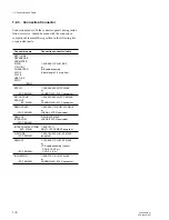
1-3. Installation
1-3-1. Installation Conditions
Operating temperature:
5
d
C to +40
d
C
Storage temperature:
-20
d
C to +50
d
C
Humidity:
No condense
• Install the unit in a location as dry and well-ventilated as
possible.
• Do not install the unit in the following conditions.
High temperature room or near the heat source
Excessive dust or mechanical vibration
Intense magnetic and electric field
A place subjected to direct sunlight or strong light
Note on installation
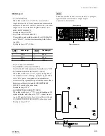
: Set the voltage selecters accord-
ing to a destination.
As for the setting, refer to “2-1-6.
Replacement of Power Unit”.
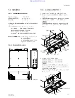
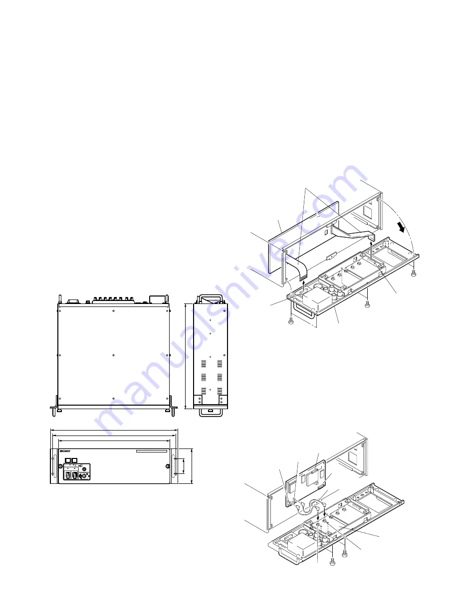
1-3-2. Outside Dimension
1-3. Installation
CABLE
ALARM
SHORT OPEN
MAIN
CAMERA
POWER
I
O
POWER
I
O
MIC
DYNAMIC
OFF
CARBON
INTERCOM
PUSH
CAMERA CONTROL UNIT
400
424
132
(Unit : mm)
57.2
465
481
1-3-3. Installation of BKP-7312
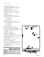
1.
Set the S250-1 switch on the BKP-7312 to OFF.
2.
Remove the six screws (B3
x
5) and then remove the
rear panel.
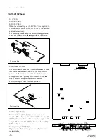
3.
Disconnect the connector CN4 on the CN-1014 board
and the connector CN3 on the CN-1049 board.
n
When disconnecting the flexible card wires, refer to
“2-1-3. Disconnecting/Connecting of Flexible Card
Wire.”
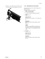
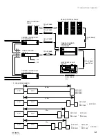
4.
Connect the two coaxial cables.
RET1/CN-1015 board — CN1/BKP-7312
RET2/CN-1015 board — CN2/BKP-7312
n
Removing the CN-1015 board makes cable connec-
tions easier. The CN-1015 board is secured with four
screws from the rear panel.
When installing the board, apply locking compound to
the four screws.
B3
×
5
B3
×
5
B3
×
5
Rear panel
MB-563 board
Flexible card wires
CN-1014 board
CN4
CN-1049 board
CN3
BKP-7312
CN2
CN1
Coaxial cable
RET2
RET1
CN-1015 board
B3
×
5
B3
×
5
A side


