2-1
CCU-700A(CU)
CCU-700AP(CE)
Section 2
Service Overview
2-1. Replacement of Main Parts
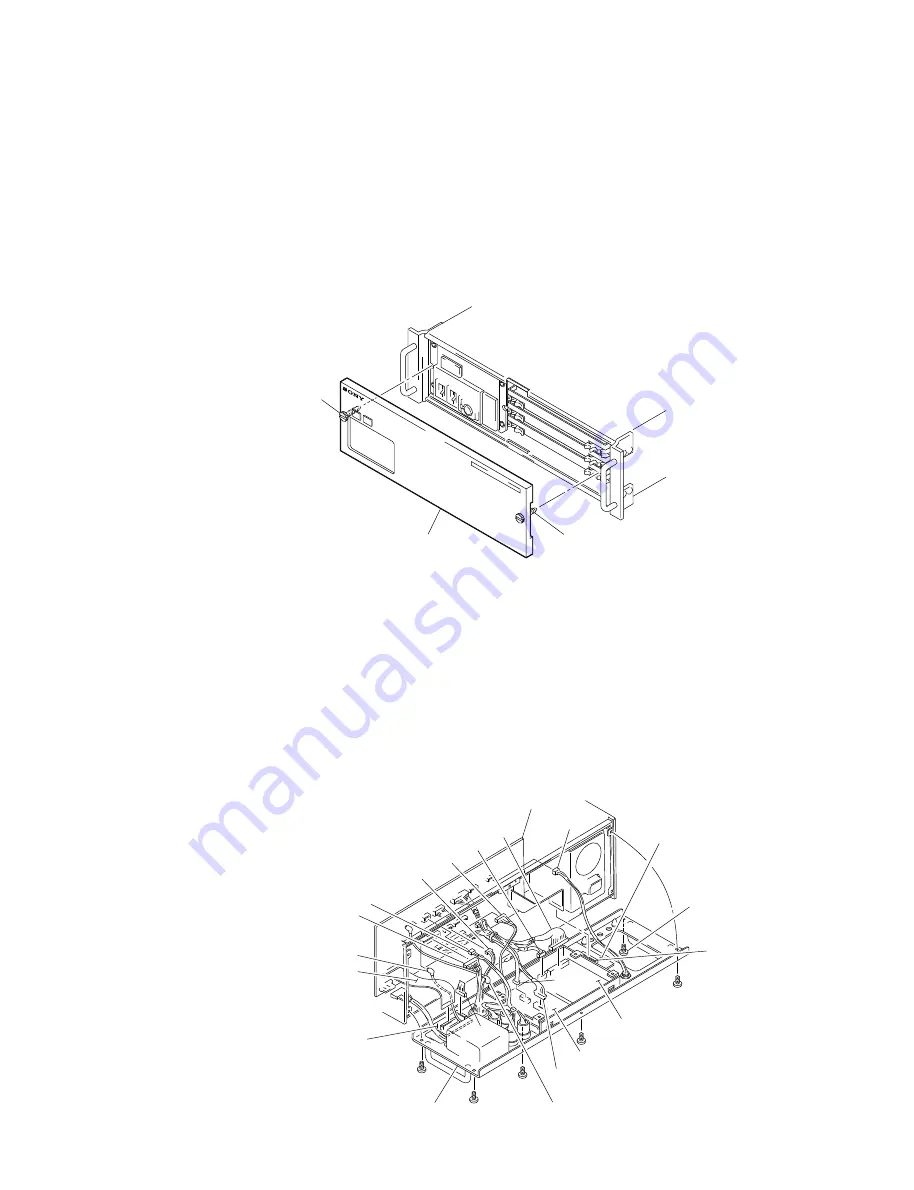
2-1-1. Removal of Front Panel
1.
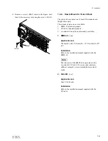
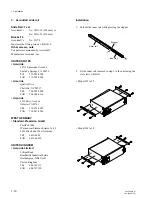
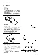
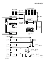
Loosen the two screws to remove the front panel.
n
Stoppers are provided for these screws.
2-1-2. Removal of Rear Panel
1.
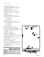
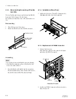
Removal the six screws (+B3
x
5) and open the rear
panel.
2.
Disconnect the eight connectors from the rear panel;
CN3,4/CN-1014 board, CN17,18/CN-1015 board,
CN18,19/CN-1036 board, CN3/CN-1049 board and
RF connector.
3.
Disconnect the seven connectors (CN10, 12, 16,17, 20,
21, 24) from the MB-563 board.
M4
×
20
M4
×
20
Front panel
CN12
CN10
CN-1014 board
B3
×
5
B3
×
5
B3
×
5
B3
×
5
CN18
B3
×
5
CN4
CN16
CN21
CN20
CN17
CN19
CN18
MB-563 board
CN24
CN-1049 board
B3
×
5
CN3
CN-1036 board
CN-1015 board
CN17
RF connector
Rear panel
CN3

