D-F200/F201
18
18
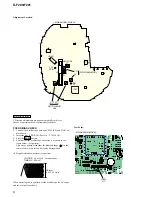
OPTICAL
PICK-UP
BLOCK
(DAX-25E)
1-684-532-
11
(11)
1 BLK
2 ORG
M502
SPINDLE
MOTOR
S803
HOLD
1 BLK
2 WHT
M501
SLED
MOTOR
OFF ON
1
A
B
C
D
E
F
G
H
I
J
2
3
4
5
6
7
8
9
10
11
12
TP4
TP81
TP419
TP416
TP85
TP3
R74
C86
D801
Q54
Q53
C43
TAP801
C5
R72
R70
R68
D81
L404
L312
L403
CT3
C9
CT1
C8
C33
C28
R69
C27
IC51
C7760
41
61
80
1
20
21
40
C101
C39
R857
C19
C78
C76
C84
C85
R646
C204
C434
C104
C318
C50
C426
C431
C419
C418
C421
C420
C406
C438
C439
C361
C52
C51
C53
C353
R432
C54
R441
R858
C55
R854
R8
C352
R56
R84
R83
R450
Q401
D409
D410
Q402
C35
Q404
R210
CN502
CN503
VDR402
R805
L310
C82
R427
R434
R433
R645
L401
R315
R413
C435
C443
C201
FB11
FB12
D82
Q409
R853
VDR403
R353
R110
R448
R445
R447
R435
R418
R414
TAP802
R411
R431
R453
R437
R417
R440
C360
R25
R806
R852
CN501
R101
L409
D305
R316
R201
R314
D301
C362
R313
R471
R828
C444
1 2
1 2
X51
T81
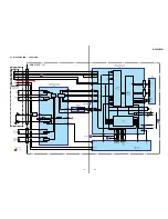
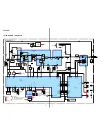
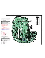
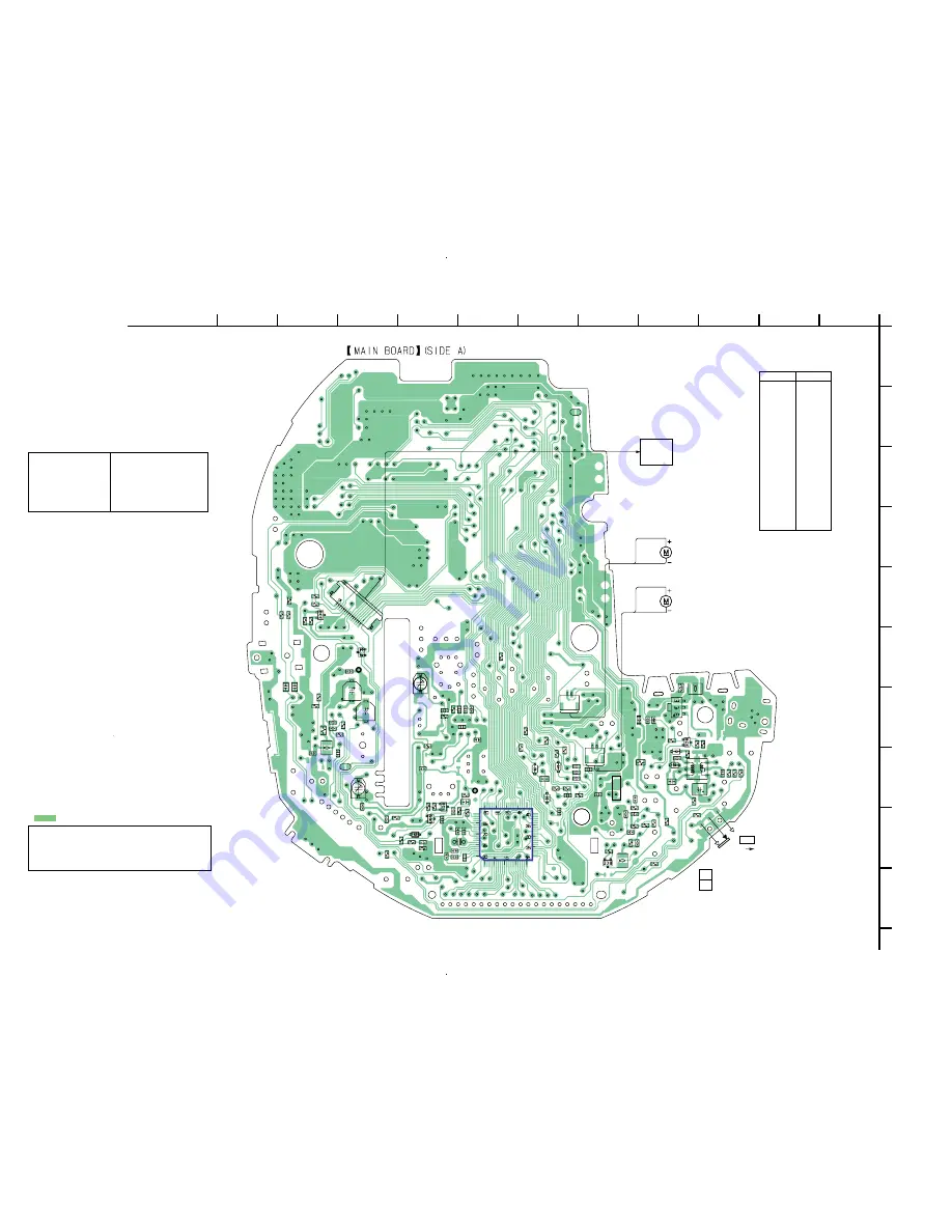
5-5. PRINTED WIRING BOARD — MAIN SECTION —
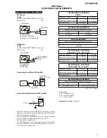
Common Note on Printed Wiring Boards:
•
X
: parts extracted from the component side.
•
Y
: parts extracted from the conductor side.
•
a
: Through hole.
•
f
: internal component.
•
: Pattern from the side which enables seeing.
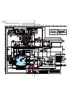
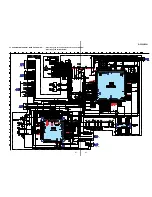
Common Note on Schematic Diagram:
• All capacitors are in µF unless otherwise noted. pF: µµF
50 WV or less are not indicated except for electrolytics
and tantalums.
• All resistors are in
Ω
and
1
/
4
W or less unless otherwise
specified.
•
%
: indicates tolerance.
•
f
: internal component.
•
C
: panel designation.
•
A
: B+ Line.
• Total current is measured with CD installed.
• Power voltage is dc 4.5 V and fed with regulated dc power
supply from external power voltage jack.
• Voltages and waveforms are dc with respect to ground in
playback mode.
no mark : FM
(
) : AM
<
> : CD
∗
: Impossible to measure
• Voltages are taken with a VOM (Input impedance 10 M
Ω
).
Voltage variations may be noted due to normal produc-
tion tolerances.
• Waveforms are taken with a oscilloscope.
Voltage variations may be noted due to normal produc-
tion tolerances.
• Circled numbers refer to waveforms.
• Signal path.
F
: FM
f
: AM
J
: CD
• Abbreviation
CND : Canadian model.
E13
: AC 220 – 230V area in E model.
E92
: AC 120V area in E model.
AUS
: Australian model.
CH
: Chinese model.
FR
: French model.
CET
: East European & CIS model.
MX
: Mexican model.
AR
: Argentina model.
Caution:
Pattern face side: Parts on the pattern face side seen from the
(Side B)
pattern face are indicated.
Parts face side:
Parts on the parts face side seen from the
(Side A)
parts face are indicated.
• Abbreviation
CND : Canadian model.
E13
: AC 220 – 230V area in E model.
E92
: AC 120V area in E model.
AUS
: Australian model.
FR
: French model.
MX
: Mexican model.
AR
: Argentina model.
Note:
The components identi-
fied by mark
0
or dotted
line with mark
0
are criti-
cal for safety.
Replace only with part
number specified.
Note:
Les composants identifiés par
une marque
0
sont critiques
pour la sécurité.
Ne les remplacer que par une
piéce portant le numéro
spécifié.
• Semiconductor
Location (Side A)
D81
G-4
D82
H-4
D301
I-8
D305
F-9
D409
H-6
D410
H-6
D801
H-6
IC51
I-7
Q53
I-8
Q54
H-8
Q401
G-4
Q402
G-4
Q404
E-10
Q409
I-5
VDR402
G-4
VDR403
H-5
Ref. No.
Location

