— 9 —
SECTION 3
DISASSEMBLY
Note :
Follow the disassembly procedure in the numerical order given.
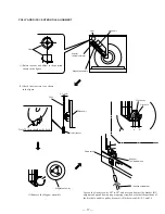
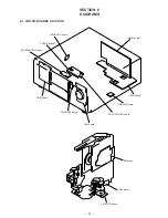
3-1. FRONT PANEL ASSEMBLY
3
Two screws (BVTT 3x6)
2
Three screws (BVTT 3x6)
4
Flat type wire (CN601)
1
Connector
(CN501)
3
Five screws
(BVTT3x6)
4
Screw
(BVTP3x10)
2
Four screws (BVTT 3x6)
6
Back panel
5
Remove the PC board holder
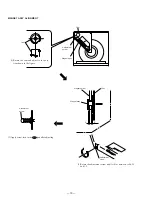
3-2. BACK PANEL ASSEMBLY
7
Front panel assembly
1
Two screws
(BVTP 3x8)
6
Remove the claw
5
Remove the claw
Summary of Contents for CDP-CX200
Page 5: ... 5 PX This section is extracted from instruction manual ...
Page 6: ... 6 ...
Page 7: ... 7 ...
Page 8: ... 8 ...
Page 11: ... 11 3 5 BASE UNIT ASSEMBLY 1 Screw BVTT3x6 2 Fulcrum plate BU UPPER assy 3 Base unit ...
Page 27: ......
Page 28: ......
Page 29: ......
Page 30: ......
Page 31: ......
Page 32: ......
Page 48: ......
Page 49: ......
Page 50: ......
Page 51: ......
Page 52: ......
Page 53: ......
Page 54: ......
Page 55: ......
Page 56: ......
Page 57: ......
Page 58: ......
Page 59: ......
Page 60: ......
Page 61: ......
Page 62: ......
Page 63: ......
Page 64: ......
Page 65: ......
Page 66: ......
Page 67: ......


